Home

Friday, June 17, 2022

Pioneer SX-3800 Receiver Restoration

Unit: AM/FM Stereo Receiver
Manufacturer: Pioneer
Model: SX-3800
SN: BC3622209S

Today I'm showcasing a Pioneer SX-3800 vintage receiver that came in for restoration. The SX-3800 was manufactured from 1980 to 1981. At this time, technology was slowly moving from analog to digital. The SX-3800 has an analog tuning dial along with a blue fluorescent display. The quartz-locked FM tuner provides excellent selectivity, low distortion, and stable reception. The reception frequency display indicates the frequency of the broadcasting station in five digits. It helps to tune quickly in a station.  A logarithmic power meter allows a power output level display from 0.01 watts up to 80 watts without range selection on a bar graph display. A non-switching amplifier system employed in SX-3800 controls the output transistor bias at a high speed in accordance with the level of the output signal. It prevents the output transistors from being set to the cut-off mode and helps eliminate higher harmonic distortion. As a result, the SX-3800 delivers a continuous power output of 60 watts per channel into an 8 ohms load from 20 to 20 kHz with no more than 0.005% total harmonic distortion.

According to the Pioneer database, this particular unit was manufactured in March 1981.

Pioneer SX-3800_After Restoration

This unit came in with multiple issues.
  1. The DC voltage measured across the speaker terminals is about 15mV on the right channel but was bouncing around 1V on the left channel. As a result, the protection relay clicks on and off cutting out the sound in both channels. Troubleshooting: the faulty HA12017 integrated circuit installed on the tone control board was replaced with a new one (refer to the "Tone Control Board") section for more detail.
  2. There is pretty noticeable static in the left channel. Troubleshooting: the faulty HA12017 integrated circuit installed on the tone control board was replaced with a new one (refer to the "Tone Control Board") section for more detail.
  3. No audio in FM mode if the FM Muting switch is in the ON position. Troubleshooting: this issue was resolved during the FM tuner alignment. The DC voltage between terminals 8 and 9 on the tuner assembly was around 2.64V. The N core of T2 was adjusted to 0V according to the service manual. 
Power Supply Board (GWR-122B)

The SX-3800 is certainly not a service-friendly receiver. A finned-style aluminum heat sink is mounted on the chassis between the power supply and power amplifier boards. As a result, the access to the foil side of both PCB's is limited and the heat sink should be disassembled from the chassis.

Finned-style aluminum heat sink

Pioneer SX-3800_Heat Sink

Heat sink removed

Pioneer SX-3800_Heat Sink removed

The power supply board (GWR-122B) has fifteen aluminum electrolytic capacitors C202, C203, C206 thru C210, C213 thru C217, C219, C223, and C227. All of them were replaced with low impedance and high-reliability Nichicon UPW/UPM caps. The max operating voltage was increased one step up on several e-caps.

The original electrolytic capacitors removed from this board have been tested with an Atlas ESR70 capacitance meter and the results are shown below. They are all still within +/- 20% of the factory capacitance tolerance and have fairly low ESR values. This is not a bad result, considering the age of this unit and the rather extreme operating conditions of the power supply board.

Test results on original capacitors removed from the power supply board:

C202: rated capacitance – 220uF, measured – 231uF, ESR – 0.01Ω, deviation: +5%
C203: rated capacitance – 220uF, measured – 228uF, ESR – 0.01Ω, deviation: +4%
C206: rated capacitance – 10uF, measured – 12uF, ESR – 1.12Ω, deviation: +20%
C207: rated capacitance – 47uF, measured – 47uF, ESR – 0.24Ω, deviation: 0%
C208: rated capacitance – 47uF, measured – 45uF, ESR – 0.28Ω, deviation: -4%
C209: rated capacitance – 47uF, measured – 47uF, ESR – 0.32Ω, deviation: 0%
C210: rated capacitance – 47uF, measured – 49uF, ESR – 0.27Ω, deviation: +4%
C213: rated capacitance – 470uF, measured – 447uF, ESR – 0.06Ω, deviation: -5%
C214: rated capacitance – 470uF, measured – 460uF, ESR – 0.04Ω, deviation: -2%
C215: rated capacitance – 1000uF, measured – 961uF, ESR – 0.01Ω, deviation: -4%
C216: rated capacitance – 100uF, measured – 112uF, ESR – 0.24Ω, deviation: +12%
C217: rated capacitance – 220uF, measured – 222uF, ESR – 0.12Ω, deviation: +1%
C219: rated capacitance – 470uF, measured – 520uF, ESR – 0.12Ω, deviation: +11%
C223: rated capacitance – 2.2uF, measured – 2.4uF, ESR – 1.27Ω, deviation: +9%
C227: rated capacitance – 10uF, measured – 11uF, ESR – 1.37Ω, deviation: +10%

All transistors on this (board except for Q202 and Q206) have also been replaced to improve the reliability of the power supply. They should be retired after working hard for the last 40+ years. Below is a list of original and replacement transistors I have used. Three transistors Q201, Q205, and Q209 are mounted on the heat sink. The old thermal pads were replaced with new Mica ones. The old thermal compound was refreshed with a new silicone thermal compound (Wakefield-Vette, 120 series).

Q201: NPN, 2SD313 (original), replaced with Fairchild MJE15032G
Q202: JFET, 2SK34 (original), retain, rarely fails
Q203: NPN, 2SC2320 (original), replaced with Fairchild KSC2383YTA
Q204: NPN, 2SC1915 (original), replaced with Fairchild KSC2690AYSTU
Q205: PNP, 2SB682 (original), replaced with Fairchild MJE15033G
Q206: JFET, 2SK34 (original), retain, rarely fails
Q207: PNP, 2SA912 (original), replaced with Fairchild KSA1013YBU
Q208: PNP, 2SA905 (original), replaced with Fairchild KSA1220AYS
Q209: NPN, 2SD313 (original), replaced with Fairchild MJE15032G
Q210: NPN, 2SD313 (original), replaced with Fairchild MJE15032G
Q211: NPN, 2SC2320 (original), replaced with Fairchild KSC2383YTA

Test results on the power supply board after servicing (FM program source, no signal):

pin 1: schematic: N/A, measured: 51.5VAC
pin 2: schematic: N/A, measured: 51.5VAC
pin 3: schematic: 0V, measured: 0V (ground)
pin 4: schematic: N/A, measured: 12.7VDC, 11.4VAC
pin 5: schematic: N/A, measured: 12.7VDC, 1.6VAC
pin 6: schematic: N/A, measured: +12.7V (Pilot lamps, PL1~3; Switch assembly, pin 1)
pin 7: schematic: N/A, measured: +12.7V (Pilot lamps, PL1~3; Switch assembly, pin 6)
pin 8: schematic: N/A, measured: 1.6VAC (FL tube, POWER, V2)
pin 9: schematic: N/A, measured: 1.6VAC (FL tube, POWER, V2)
pin 10: schematic: 0V, measured: 0V (ground)
pin 11: schematic: N/A, measured: 1.6VAC (FL tube, FREQUENCY, V1)
pin 12: schematic: N/A, measured: 1.6VAC (FL tube, FREQUENCY, V1)
pin 13: schematic: N/A, measured: +29.2V (Power Amp, pin 6)
pin 14: schematic: +19.5V, measured: +23.5V (Q11, pin 16)
pin 15: schematic: +12.8V, measured: +13.5V (Equalizer, pin 11)
pin 16: schematic: N/A, measured: +12.7V (Equalizer, pin 10)
pin 17: schematic: +5.5V, measured: +5.3V (Equalizer, pin 12)
pin 18: schematic: -47V, measured: -47.3V (Power Amp, pin 1)
pin 19: schematic: 0V, measured: 0V (ground)
pin 20: schematic: +47V, measured: +46.8V (Power Amp, pin 7)
pin 21: schematic: 0V, measured: 0V (ground)
pin 22: schematic: +32V, measured: +31.9V (Tone Control, pin 47; Equalizer, pin 1)
pin 23: schematic: -32V, measured: -32.6V (Tone Control, pin 46; Equalizer, pin 2)
pin 24: schematic: N/A, measured: -21.3V (Indicator Assembly, pin 4)
pin 25: schematic: -13V, measured: -14.2V (Tuner assembly, pin 2)
pin 26: schematic: N/A, measured: 34.4VAC
pin 27: schematic: N/A, measured: 34.4VAC
pin 28: schematic: 0V, measured: 0V (ground)
pin 29: schematic: +45.5V, measured: +45.6V (Power Amp, pin 31)
pin 30: schematic: 0V, measured: 0V (ground)
pin 31: schematic: -45.5V, measured: -45.6V (Power Amp, pin 32)
pin 32: schematic: 0V, measured: 0V (ground)
pin 33: schematic: 0V, measured: 0V (ground)
pin 34: schematic: 0V, measured: 0V (ground)
pin 35: schematic: +45.5V, measured: +45.6V (Power Amp, pin 14)
pin 36: schematic: 0V, measured: 0V (ground)
pin 37: schematic: -45.5V, measured: -45.6V (Power Amp, pin 13)

Power supply board - before and after servicing (sorry, I took a bad picture of this board due to a bunch of wires)

Pioneer SX-3800_Power Supply (GWR-122B)_before servicing

Pioneer SX-3800_Power Supply (GWR-122B)_after servicing

Filter Capacitors

I performed an in-circuit test on two large filter capacitors with Atlas ESR70 capacitance meter. Both caps are still within the factory capacitance tolerance and have very low ESR. So, I didn't change them. In general, the filter capacitors rarely fail in vintage gears, and I usually don't replace them unless their ESR is high.

In-circuit test on two filter capacitors - both are still in spec

C225: rated capacitance – 12000uF, measured – 11150uF, ESR – 0.02Ω, deviation: -7%
C226: rated capacitance – 12000uF, measured – 11620uF, ESR – 0.02Ω, deviation: -3%

Power Amplifier (GWH-139)

The power amplifier board has two low leakage e-caps (C101, C102) installed in the signal path, two bi-polar e-caps (C125, C126), and two aluminum electrolytic capacitors (C133, C134) installed in the protection circuit. The original low leakage e-caps were replaced with modern low leakage Nichicon UKL caps. Two bi-polar e-caps were replaced with replaced with film polyester Kemet caps. Finally, two aluminum e-caps were replaced with low impedance Nichicon UPW caps.

Test results on original capacitors removed from the power amplifier board:

C101: rated capacitance – 4.7uF, measured – 5.1uF, ESR – 2.5Ω, deviation: +9%
C102: rated capacitance – 4.7uF, measured – 5.0uF, ESR – 2.3Ω, deviation: +6%
C125: rated capacitance – 0.22uF, measured – 0.25uF, ESR – N/A, deviation: +14%
C126: rated capacitance – 0.22uF, measured – 0.25uF, ESR – N/A, deviation: +14%
C133: rated capacitance – 470uF, measured – 491uF, ESR – 0.11Ω, deviation: +5%
C134: rated capacitance – 100uF, measured – 97uF, ESR – 0.31Ω, deviation: -3%

Four transistors (Q109, Q110, Q115, and Q116) installed on the power amplifier board get very hot under normal operating conditions. The original transistors installed in these positions are 2SC1915 (Q109, Q110, NPN) and 2SA905 (Q115, Q116, PNP). The package type of original transistors is TO-92 with a thick collector lead, 0.84mm. The maximum collector power dissipation is 0.8W, which is insufficient for efficient heat dissipation. As a result, the long-term reliability of these transistors is always in doubt. I replaced the NPN transistors with a Fairchild KSC2690 and the PNP transistors with a Fairchild KSA1220. The maximum collector power dissipation of the new Fairchild transistors is 1.2W, which contributes to long-term reliability.

The original relay driver transistor on this board is 2SC1384. It usually degrades over time and I replaced it with a new Fairchild KSC2690. The new transistor has the same pinout as the original one. I tested the original transistor with Atlas DCA55 semiconductor analyzer and the measured current gain was only 63. According to the datasheet, the minimum gain for this transistor is supposed to be at least 120 (2SC1384, rank R). So, it always makes sense to replace the original relay driver transistor with a new one.

The original trimming resistors VR1/VR2 (470 kΩ, DC offset), VR3/VR4 (100 Ω, Bias), and VR5/VR6 (100 kΩ, Bias) were replaced with new Bourns potentiometers.

Power amplifier board - before and after servicing

Pioneer SX-3800_Power Amp (GWH-139)_before servicing

Pioneer SX-3800_Power Amp (GWH-139)_after servicing

Tone Control Board (GWG-141A)

The tone control board is probably the easiest board for servicing in comparison to all other PCBs in Pioneer SX-3800. However, to get the best access one should remove the front panel, disassemble the panel frame and remove three ribbon cables. Looks like a lot of work but the panel frame should be disassembled from the chassis in any case to get access to all controls. Otherwise, it is impossible to clean and lubricate all pots and switches behind this frame.

The front panel and panel frame removed

Pioneer SX-3800_Front Panel and Panel Frame removed

As I mentioned earlier, the DC voltage measured across the speaker terminals in this receiver was about 15mV on the right channel but fluctuated around 1V on the left channel. Initial diagnostics revealed a defective HA12017 integrated circuit installed in the left channel. The voltage measured on pins 1, 6, and 7 of Q1 (left channel) was different from the reference voltage on the schematic. In addition, the voltage on pin 6 was unstable and fluctuated around 3 V. The voltage measured on all pins of Q2 (right channel) was very close to the reference voltage on the schematic. I replaced the faulty HA12017 with a new one from old stock and normal operation was restored. The voltage across the speaker terminals on the left channel has stabilized at around 22mV. The static in the left channel has disappeared and the protection relay stopped clicking on and off.

Test results on HA12017 (Q1 & Q2) - the IC from the left channel is defective:

pin 1: schematic: 0V, measured: +25.9V (left); 61mV (right)
pin 3: schematic: N/A, measured: +20V (left); +19.5 (right)
pin 4: schematic: -25V, measured: -27.6V (left); -26.1 (right)
pin 5: schematic: N/A, measured: -28V (left); -24.9V (right)
pin 6: schematic: 0V, measured: -3V (left); 78mV (right)
pin 7: schematic: 0V, measured: +8.8V (left); 80mV (right)
pin 8: schematic: +25V, measured: +27.2V (left); +25.5 (right)

Test results on HA12017 (Q1 & Q2) after replacement the defective IC with a new one:

pin 1: schematic: 0V, measured: 40mV (left); 61mV (right)
pin 3: schematic: N/A, measured: +20.1V (left); +19.6 (right)
pin 4: schematic: -25V, measured: -25.9V (left); -26.2 (right)
pin 5: schematic: N/A, measured: -24.7V (left); -24.9V (right)
pin 6: schematic: 0V, measured: 53mV (left); 78mV (right)
pin 7: schematic: 0V, measured: 54mV (left); 80mV (right)
pin 8: schematic: +25V, measured: +25.3V (left); +25.6V (right)

The tone control board has fourteen low leakage e-caps (C1, C2, C15 thru C18, C21, C22, C25 thru C28, C33, C34) and eight aluminum e-caps (C7, C8, C13, C14, C 29 thru C32). All original low leakage e-caps with the rated capacitance of 1uF and lower were replaced with high-quality film polyester caps (WIMA and Kemet). The low leakage e-caps with higher rated capacitance were replaced with modern low leakage Nichicon UKL capacitors. The remaining aluminum e-caps were replaced with low impedance Nichicon UPW caps.  

Test results on original capacitors removed from the tone control board:

C1: rated capacitance – 4.7uF, measured – 5.1uF, ESR – 1.8Ω, deviation: +9%
C2: rated capacitance – 4.7uF, measured – 5.1uF, ESR – 2.0Ω, deviation: +9%
C7: rated capacitance – 100uF, measured – 100uF, ESR – 0.46Ω, deviation: 0%
C8: rated capacitance – 100uF, measured – 100uF, ESR – 0.48Ω, deviation: 0%
C13: rated capacitance – 47uF, measured – 43uF, ESR – 0.59Ω, deviation: -9%
C14: rated capacitance – 47uF, measured – 43uF, ESR – 0.66Ω, deviation: -9%
C15: rated capacitance – 0.22uF, measured – 0.22uF, ESR – N/A, deviation: 0%
C16: rated capacitance – 0.22uF, measured – 0.21uF, ESR – N/A, deviation: -5%
C17: rated capacitance – 1uF, measured – 1uF, ESR – 3.6Ω, deviation: 0%
C18: rated capacitance – 1uF, measured – 1uF, ESR – 4.0Ω, deviation: 0%
C21: rated capacitance – 0.33uF, measured – 0.35uF, ESR – N/A, deviation: 0%
C22: rated capacitance – 0.33uF, measured – 0.35uF, ESR – N/A, deviation: 0%
C25: rated capacitance – 1uF, measured – 1uF, ESR – 4.2Ω, deviation: 0%
C26: rated capacitance – 1uF, measured – 1.1uF, ESR – 4.2Ω, deviation: +10%
C27: rated capacitance – 10uF, measured – 11uF, ESR – 0.54Ω, deviation: +10%
C28: rated capacitance – 10uF, measured – 11uF, ESR – 0.52Ω, deviation: +10%
C29: rated capacitance – 47uF, measured – 48uF, ESR – 0.28Ω, deviation: +2%
C30: rated capacitance – 47uF, measured – 48uF, ESR – 0.22Ω, deviation: +2%
C31: rated capacitance – 47uF, measured – 48uF, ESR – 0.23Ω, deviation: +2%
C32: rated capacitance – 47uF, measured – 50uF, ESR – 0.22Ω, deviation: +6%
C33: rated capacitance – 10uF, measured – 11uF, ESR – 0.46Ω, deviation: +10%
C34: rated capacitance – 10uF, measured – 11uF, ESR – 0.52Ω, deviation: +10%

Tone control board - before and after servicing

Pioneer SX-3800_Tone Control (GWG-141)_before servicing

Pioneer SX-3800_Tone Control (GWG-141)_after servicing

Equalizer Amplifier Board (AWM-227A)

To service this board, one should remove four plastic arms for the function controls, four ribbon cables, and then disassemble it from the rear panel.

The equalizer amplifier board has four low leakage capacitors (C3, C4, C23, C24) installed in the signal path, and six aluminum e-caps (C1, C2, C9, C10, C21, C22). The low leakage capacitors were replaced with modern low leakage Nichicon UKL capacitors. And the remaining aluminum e-caps were replaced with low impedance Nichicon UPW caps.

Test results on original capacitors removed from the equalizer amplifier board:

C1: rated capacitance – 47uF, measured – 49uF, ESR – 0.34Ω, deviation: +4%
C2: rated capacitance – 47uF, measured – 50uF, ESR – 0.27Ω, deviation: +6%
C3: rated capacitance – 4.7uF, measured – 5.1uF, ESR – 1.81Ω, deviation: +9%
C4: rated capacitance – 4.7uF, measured – 5.0uF, ESR – 2.21Ω, deviation: +6%
C9: rated capacitance – 470uF, measured – 557uF, ESR – 0.09Ω, deviation: +19%
C10: rated capacitance – 470uF, measured – 511uF, ESR – 0.08Ω, deviation: +9%
C21: rated capacitance – 47uF, measured – 49uF, ESR – 0.27Ω, deviation: +4%
C22: rated capacitance – 47uF, measured – 48uF, ESR – 0.26Ω, deviation: +2%
C23: rated capacitance – 4.7uF, measured – 5.1uF, ESR – 1.89Ω, deviation: +9%
C24: rated capacitance – 4.7uF, measured – 5.1uF, ESR – 2.81Ω, deviation: +9%

Equalizer amplifier board - before and after servicing

Pioneer SX-3800_Equalizer Amp (AWM-227A)_before servicing

Pioneer SX-3800_Equalizer Amp (AWM-227A)_after servicing

FL Indicator Board (AWV-009)

To release this board for servicing one should disassemble a lot of stuff: the front panel, the panel frame, and the dial panel. In that case, it is possible to service this board without a dial cord re-stringing. It is still not an easy task but doable with a lot of patience and luck.

Tough access to the FL indicator board

Pioneer SX-3800_FL Indicator Board (AWV-009)_tough access

The FL indicator board has two low leakage capacitors (C1, C2) and 12 aluminum e-caps (C3, C10, C16, C28, C31, C33 thru C39). The original low leakage e-caps as well as aluminum e-caps C3, C33 thru C39 were replaced with film polyester WIMA caps. The remaining aluminum capacitors were replaced with low impedance Nichicon UPW caps.

Test results on original capacitors removed from the equalizer amplifier board:

C1: rated capacitance – 1uF, measured – 1uF, ESR – 4.7Ω, deviation: 0%
C2: rated capacitance – 1uF, measured – 1uF, ESR – 4.1Ω, deviation: 0%
C3: rated capacitance – 0.47uF, measured – 0.52uF, ESR – N/A, deviation: %
C10: rated capacitance – 100uF, measured – 115uF, ESR – 0.21Ω, deviation: +15%
C16: rated capacitance – 470uF, measured – 496uF, ESR – 0.06Ω, deviation: +6%
C28: rated capacitance – 470uF, measured – 508uF, ESR – 0.07Ω, deviation: +8%
C31: rated capacitance – 220uF, measured – 203uF, ESR – 0.22Ω, deviation: -8%
C33: rated capacitance – 1uF, measured – 1uF, ESR – 1.59Ω, deviation: 0%
C34: rated capacitance – 1uF, measured – 1uF, ESR – 1.73Ω, deviation: 0%
C35: rated capacitance – 1uF, measured – 1uF, ESR – 1.72Ω, deviation: 0%
C36: rated capacitance – 1uF, measured – 1uF, ESR – 1.68Ω, deviation: 0%
C37: rated capacitance – 1uF, measured – 1uF, ESR – 1.76Ω, deviation: 0%
C38: rated capacitance – 1uF, measured – 0.9uF, ESR – 1.67Ω, deviation: -10%
C39: rated capacitance – 1uF, measured – 0.9uF, ESR – 1.65Ω, deviation: -10%

FL indicator board - before and after servicing

Pioneer SX-3800_FL Indicator (AWV-009)_before servicing

Pioneer SX-3800_FL Indicator (AWV-009)_after servicing

Dial Lamps

All original dial lamps in this unit were replaced with new incandescent lamps (8V, wedge base). Each lamp is very easy to replace without damaging the brittle lamp socket if you use the following tip below.

Tip: there is a small opening at the center of each lamp socket. I used a small Allen wrench and gently pushed each lamp out of the socket. In that case, the brittle socket tabs won't be damaged or broken.

DC offset and Bias Adjustments

At the end of my restoration, I adjusted the DC offset and Bias on the power amplifier according to the service manual.

The DC offset on the left channel is measured between pin 23 and ground. On the right channel, it is measured between pin 22 and ground. It is pretty hard to reach these two pins due to limited access. But the multimeter can be directly connected to the speaker terminals to adjust the DC offset. Just make sure to depress the switch (A or B) corresponding to the SPEAKERs terminals on the rear panel. The DC offset should be adjusted as close to zero volts as possible with the trimming resistors VR1 and VR2.

The Bias on the left channel is measured between pins 28 (+) and 25 (-). On the right channel, it is measured between pins 17 (+) and 20 (-). It should be adjusted to ~120mV with the trimming resistors VR3 and VR4. And then, to ~150mV with the trimming resistors VR5 and VR6. I adjusted the bias on each channel to about 10mV lower than the manual recommends. Based on my experience, the bias is usually drifting to higher values over time in this model (as well as in model SX-3900).

DC offset on the left and right channels after restoration

Pioneer_SX-3800_DC offset_left channel

Pioneer_SX-3800_DC offset_right channel

Bias on the left and right channels after restoration

Pioneer_SX-3800_Bias_left channel

Pioneer_SX-3800_Bias_right channel

Output Power Test

The final output power test was performed at the end of my restoration. The amplifier was loaded with a low inductance 8Ω/100W dummy resistor for each channel. The oscilloscope was connected across the speaker terminals and a sine-wave signal of 1kHz was applied to the AUX jacks. The output sine-wave signal was perfectly symmetrical on both channels with no clipping up to 22.65 VRMS (left channel) and 23.34 VRMS (right channel). It corresponds to the output power of 64.1W on the left channel and 68.1W on the right channel.

Output power test

Pioneer SX-3800_Output Power Test

As usual, all the knobs and the front panel were gently cleaned in warm water with dish soap. All controls have been cleaned with DeoxIT 5% contact cleaner and lubricated with DeoxIT FaderLube 5% spray.

The final result can be seen in the photos below. The receiver looks and sounds great again. Please watch a short demo video at the end of this post. Thank you for reading.

Pioneer SX-3800 - after restoration

Pioneer SX-3800_After Restoration

Pioneer SX-3800_After Restoration_ with parts

Demo video after repair & restoration

Friday, May 27, 2022

DLK Model 1 1/2 Loudspeaker Restoration

Unit: Loudspeaker System
Manufacturer: DLK
Model: 1 1/2
SN: 12994 & 13463

I bought these speakers a year ago from the original owner. The cabinets and grills are in excellent cosmetic condition. According to the owner, the woofers were re-foamed several years ago at Midwest Speaker Repair in Roseville, Minnesota. I didn't get a chance to test them before buying, but the seller claimed these speakers sound great. After some negotiations, we made a deal.

DLK_Model 1 1/2_After Restoration

I have read a lot of good reviews about DLK speakers on various audiophile forums but I have never owned them. DLK speakers were designed by Don L. Kliewer and built in Minnesota. To the best of my knowledge, there were many variations of the 1 1/2's over the years of production. This pair has woofers with rubber surrounds, DLK dust caps, phenolic ring tweeter, black foam padded grills, and solid wood cabinets.

There are also two versions of the 1 1/2 model with an impedance of 4 ohms and 8 ohms. This pair of speakers have a 4 Ohm impedance. 

I believe this is the 1st generation of DLK 1 1/2  speakers with the round terminal plate. Below is a specification for model 1 1/2 from the DLK brochure.

Woofer: two 8'' high compliance with low-mass cones
Tweeter: one 1 1/2'' direct-radiating
Frequency response: from 40Hz to 18.5kHz
Crossover network: 1st order series type. 6dB/octave slope. The 3000Hz crossover point is above the most critical midrange frequencies
Impedance: 4 Ohms
Recommended minimum amplifier power: 15 Watts
Recommended maximum amplifier power: 80 Watts
Cabinet dimensions: 24'' (H) x 14 1/2'' (W) x 12'' (D)
Weight: 38.5 pounds

So, before hooking up, I measured the impedance of each speaker to make sure there weren't any surprises. The measured impedance was about 4 Ohms. I then hooked them up to my Pioneer SX-770 receiver that I had recently restored, and... And I was very disappointed! The sound was coming only from the woofers but the tweeter was silent. I twisted the L-pad back and forth a few times but didn't notice any change. I pulled out the tweeter from each speaker and tested it. As expected, both tweeters are blown. I also pulled out the woofers and tested them as well. Fortunately, all woofers are still good.

I decided to restore these speakers and bought new tweeters from the Midwest Speaker Repair. The replacement part number is MT-4107-4. This is an exact replica of the original tweeter for this model. 

The original L-pads and capacitors in the crossover were also upgraded. I bought new L-pads from the Parts Express. The replacement part number is 260-255 (50W Mono, 1'' shaft, 8 Ohm). 

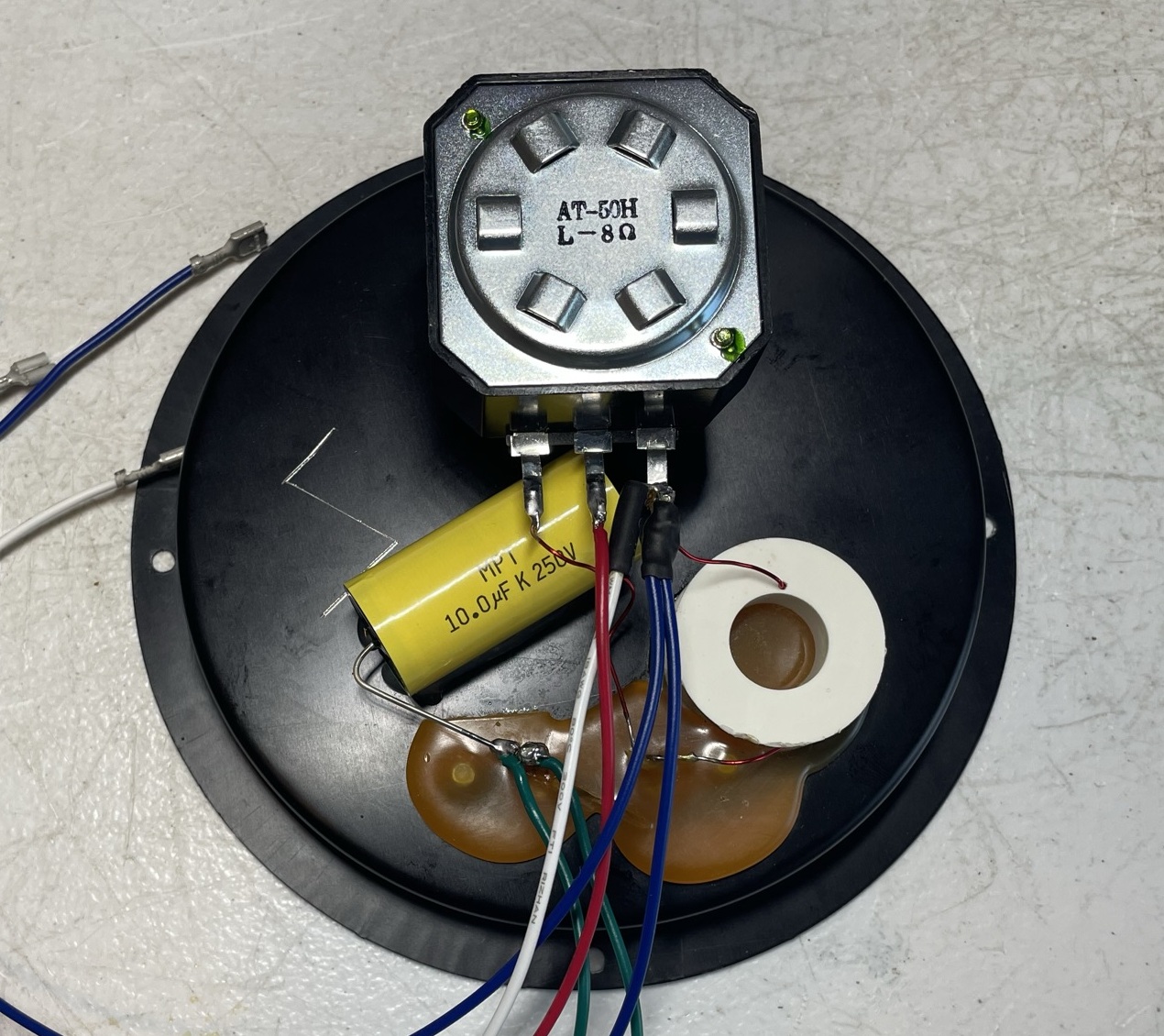
The original bipolar capacitor (10uF/50V) was replaced with a new MPT (metalized polypropylene film) cap made by SuperTech. This is a self-healing capacitor, rated from -40°C to 105°C with a capacitance tolerance of +/- 10%. 

Finally, all original wires were also replaced since I noticed the oxidation on several crimps. I used the 18 AWG stranded wires. I believe the original wires are 20 AWG stranded wires (no marking on them). New crimps are TE Connectivity, the part number is 42710-2.

The cabinets are still in perfect condition, with no scratches or dents. So, I just treated the cabinets to some Restore-a-Finish and Feed-n-Wax.

Below are some photos I took during my restoration process. The final result is amazing! The sound is smooth, with great detail, strong and tight bass, good midrange, and clear highs. These are very underrated speakers from the 70's. Please watch a short demo video at the end of this post. Thank you for reading.

DLK 1 1/2 Network wiring schematic

DLK_Model 1 1/2_Network Wiring Schematic

Both tweeters are blown

DLK_Model 1 1/2_Twetter_Blown

Original woofer with green frame and green cone - still in excellent shape

DLK_Model 1 1/2_Woofer_Original with green frame

Original crossover

DLK_Model 1 1/2_Crossover_Original

Crossover with new L-Pad and MPT capacitor

DLK_Model 1 1/2_Crossover_New L-Pad and MPT capacitor

Round terminal plate

DLK_Model 1 1/2_Terminal Plate

Replaced parts

DLK_Model 1 1/2_Replaced parts

DLK Model 1 1/2 - after restoration

DLK_Model 1 1/2_After Restoration

DLK_Model 1 1/2_After Restoration_with grills

DLK_Model 1 1/2_Back Side

Demo video after repair & restoration

Sunday, May 1, 2022

Pioneer SX-950 Receiver Restoration

Unit: AM/FM Stereo Receiver
Manufacturer: Pioneer
Model: SX-950
SN: XH2906404S

Today I'm showcasing a Pioneer SX-950 vintage receiver that came in for restoration. The SX-950 is a high-end offering from Pioneer's most famous product line, the SX-X50 series. It was initially introduced in 1976 and made through 1978. It delivers a continuous power output of 85 watts per channel into an 8 ohms load from 20 to 20 kHz with no more than 0.1% total harmonic distortion. 

The SX-950 looks very similar to SX-850 which I serviced a few months ago. The only difference is the number of speaker terminals. The SX-950 has three speaker terminals (A, B, and C) while the SX-850 has only two (A and B). Both units have the same dimensions and similar weight. Moreover, all boards except the tuner and power amplifier assembly have the same circuit design.

According to the Pioneer database, this particular unit was manufactured in August 1977.

The restoration of the smaller brothers of SX-950 can be found on my blog here:

Pioneer SX-950_After Restoration

Initial Evaluation and Troubleshooting

The protection relay in this unit was bypassed for some reason. Obviously, this is not a smart decision and should be fixed. Moreover, the previous owner (or whoever serviced this receiver before) added two additional capacitors (6800uF/71V) parallel to the main filter capacitors (22000uF/63V). Again, not a good idea. I know some technicians like the idea to upgrade the main filter capacitors with higher capacitance but I am not in favor of this modification. It potentially can increase the stress on the circuit and reduce the overall reliability. I always prefer to stick with the original circuit design. 

Also, look at the photos below. Did you notice how badly this modification was done?! Check this out: a lot of extra soldering alloy was used, the insulating sleeve on both original filter capacitors was touched with a soldering iron and melted, the insulation on some wires was also melted, and the electrical tape was used instead of shrink tubing. It's sloppy work! Well, everything should be reworked here to bring it back to its original configuration.

Protection relay bypassed, wire insulation was melted, electrical tape was used instead of shrink tubing

Pioneer_SX-950_Protection Relay Bypassed

Two additional capacitors (6800uF/71V) were added (not a good idea and sloppy work)

Pioneer_SX-950_Additional Filter capacitors

I removed the original protection relay and checked its contacts. To my surprise, all contacts were still in perfect condition. I didn't notice any degradation due to arcing. I also tested the power supply and protection unit and didn't find any substantial issues. So, not sure why the protection relay in this unit was bypassed.

I replaced the original relay with a new Omron relay (part # LY2F-DC24) and wired it according to the schematic. Then, I powered up this receiver with my Dim Bulb Tester. The light bulb flashed for a second on bright and then dimmed out almost completely. The protection relay engaged after a few seconds and a normal sound was restored. So, the unit works properly again.

A new Omron protection relay was installed

Pioneer_SX-950_Protection Relay_New Omron

After discussion with the owner, it was decided to remove additional capacitors and restore the original circuit. The original filter capacitors (22000uF/63V) were tested with Atlas ESR70 capacitance meter and are still within the factory capacitance tolerance with almost zero ESR: 18100uF/0.01Ω and 18230uF/0.01Ω. So, I rewired them and also installed new metal oxide resistors (KOA Speer, 2.7kΩ/2W). All wires with melted insulation were also replaced. The electrical tape was replaced with shrink tubing. Now, it's time to move to routine restoration.

Original (22000uF/63V) filter capacitors - rewired

Pioneer_SX-950_Original Filter Capacitors_rewired

Power Supply Board (AWR-101)

The power supply board (AWR-101) has twelve aluminum electrolytic capacitors C10 thru C16, C18 thru C21, and C23. All of them were replaced with low impedance and high-reliability Nichicon UPW/UPM caps. The max operating voltage was increased one step up on several e-caps.

The original e-caps removed from this board were tested with an Atlas ESR70 capacitance meter and the results are below. Only two out of twelve original e-caps are outside the factory capacitance tolerance +/- 20%. Not too bad in comparison to the SX-850 which I serviced a few months ago.

Test results on original capacitors removed from power supply board:

C10: rated capacitance – 470uF, measured – 370uF, ESR – 0.02Ω, deviation: -21%
C11: rated capacitance – 470uF, measured – 399uF, ESR – 0.02Ω, deviation: -15%
C12: rated capacitance – 2200uF, measured – 2120uF, ESR – 0.01Ω, deviation: -4%
C13: rated capacitance – 1000uF, measured – 1072uF, ESR – 0.01Ω, deviation: +7%
C14: rated capacitance – 47uF, measured – 53uF, ESR – 0.38Ω, deviation: +13%
C15: rated capacitance – 470uF, measured – 374uF, ESR – 0.01Ω, deviation: -20%
C16: rated capacitance – 47uF, measured – 51uF, ESR – 0.71Ω, deviation: +9%
C18: rated capacitance – 47uF, measured – 34uF, ESR – 2.6Ω, deviation: -28%
C19: rated capacitance – 47uF, measured – 56uF, ESR - 0.24Ω, deviation: +19%
C20: rated capacitance – 100uF, measured – 101uF, ESR – 0.06Ω, deviation: +1%
C21: rated capacitance – 47uF, measured – 52uF, ESR – 0.78Ω, deviation: +11%
C23: rated capacitance – 100uF, measured – 114uF, ESR - 0.16Ω, deviation: +14%

All transistors on this board were also replaced to improve the reliability of the power supply. They should be retired after working hard for the last 45+ years. Below is a list of original and replacement transistors I used. Four transistors Q1, Q2, Q8, and Q9 are mounted on the heat sink. The old thermal pads were replaced with new Mica ones. The old thermal compound was refreshed with a new silicone thermal compound (Wakefield-Vette, 120 series).

Q1: NPN, 2SD313 (original), replaced with a new Fairchild KSC2073TU
Q2: PNP, 2SB507 (original), replaced with a new Fairchild KSA940TU
Q3: NPN, 2SC1384 (original), replaced with a new Fairchild KSC2383YTA
Q4: PNP, 2SA720 (original), replaced with a new Fairchild KSA1013YBU
Q5: NPN, 2SC1384 (original), replaced with a new Fairchild KSC2690AYSTU
Q6: PNP, 2SA720 (original), replaced with a new Fairchild KSA1013YBU
Q7: NPN, 2SC1384 (original), replaced with a new Fairchild KSC2383YTA
Q8: NPN, 2SD313 (original), replaced with a new Fairchild KSC2073TU
Q9: NPN, 2SD313 (original), replaced with a new Fairchild KSD526Y
Q10: NPN, 2SC869 (original), replaced with a new Fairchild KSC2383YTA

Power supply board - before servicing

Pioneer_SX-950_Power Supply_AWR-101_before servicing_01

Pioneer_SX-950_Power Supply_AWR-101_before servicing_02

Power supply board - after servicing

Pioneer_SX-950_Power Supply_AWR-101_after servicing_01

Pioneer_SX-950_Power Supply_AWR-101_after servicing_02

Protection Unit (AWM-062-0)

The protection unit in Pioneer SX-950 (as well as in SX-850) has the same design as in Pioneer SX-1010 introduced to the market in 1974. There are two coupling capacitors (C1, C2) and four aluminum electrolytic capacitors (C3 thru C6) installed on this board. Two coupling capacitors are the notorious sky blue Sanyo e-caps. I replaced them with high-quality film polyester Kemet caps. The remaining aluminum e-caps were replaced with low impedance Nichicon UPW caps.

Test results on original capacitors removed from protection unit board:

C1: rated capacitance – 0.22uF, measured – 0.28uF, ESR – N/A, deviation: +27%
C2: rated capacitance – 0.22uF, measured – 0.28uF, ESR – N/A, deviation: +27%
C3: rated capacitance – 330uF, measured – 354uF, ESR – 0.21Ω, deviation: +7%
C4: rated capacitance – 330uF, measured – 305uF, ESR – 0.19Ω, deviation: -8%
C5: rated capacitance – 4.7uF, measured – 5.3uF, ESR – 1.57Ω, deviation: +13%
C6: rated capacitance – 100uF, measured – 114uF, ESR – 0.21Ω, deviation: +14%

The relay driver transistor Q7 suffers from the current spike every time the relay turns off. Eventually, it fails due to severe degradation. I unsoldered and tested this transistor with Atlas DCA55 semiconductor analyzer. The measured current gain was only 57. According to the datasheet, the minimum gain for this transistor is supposed to be at least 120 (2SC1384, rank R). I replaced the original 2SC1384 transistor with a new Fairchild KSC2690. The new transistor has the same pinout as the original one. Also, a fly-back safety diode (1N4004G) was added to the circuit to prevent potential output damage. The safety diode was soldered between pins 9 (anode, "+") and 10 (cathode, "-").

Protection unit - before and after

Pioneer_SX-950_Protection Unit (AWM-062)_before servicing

Pioneer_SX-950_Protection Unit (AWM-062)_after servicing

Tone Amplifier Board (AWG-039C)

The tone amplifier board installed in this unit is AWG-039, revision C. Note that two electrolytic capacitors (C29 & C30) are bypassed in revision C. The tone amplifier board has two solid tantalum capacitors (C25, C26), eight low leakage electrolytic capacitors (C13, C14, C15, C16, C19, C20, C23, C24), and two aluminum e-caps (C21, C22).

The original tantalum capacitors were replaced with film polyester Kemet caps. All original low leakage e-caps were replaced with modern low leakage Nichicon UKL caps. Finally, two aluminum filtering capacitors (C21, C22) were replaced with low impedance Nichicon UPW caps.

Test results on original capacitors removed from tone amplifier board:

C13: rated capacitance – 2.2uF, measured – 1.8uF, ESR – 3.9Ω, deviation: -18%
C14: rated capacitance – 2.2uF, measured – 1.8uF, ESR – 5.2Ω, deviation: -18%
C15: rated capacitance – 2.2uF, measured – 1.9uF, ESR – 4.4Ω, deviation: -14%
C16: rated capacitance – 2.2uF, measured – 1.8uF, ESR – 4.1Ω, deviation: -18%
C19: rated capacitance – 100uF, measured – 118uF, ESR – 0.26Ω, deviation: +18%
C20: rated capacitance – 100uF, measured – 110uF, ESR – 0.31Ω, deviation: +10%
C21: rated capacitance – 47uF, measured – 58uF, ESR – 0.11Ω, deviation: +23%
C22: rated capacitance – 47uF, measured – 61uF, ESR – 0.11Ω, deviation: +30%
C23: rated capacitance – 2.2uF, measured – 1.7uF, ESR – 4.3Ω, deviation: -23%
C24: rated capacitance – 2.2uF, measured – 1.9uF, ESR – 3.7Ω, deviation: -14%
C25: rated capacitance – 0.22uF, measured – 0.23uF, ESR – N/A, deviation: +5%
C26: rated capacitance – 0.22uF, measured – 0.23uF, ESR – N/A, deviation: +5%

Two original NPN transistors (Q1 and Q2) installed on this board are 2SC1312. This transistor is known to become very noisy over time. I replaced both original transistors with modern low noise Fairchild KSA1845. Watch the pinout on replacement transistors. The original transistor is BCE and the new one is ECB.

Tone amplifier board - before and after

Pioneer_SX-950_Tone Amp Board_AWG-039C_before servicing

Pioneer_SX-950_Tone Amp Board_AWG-039C_after servicing

Flat Amplifier Board (AWG-038)

The flat amplifier board has four low leakage e-caps installed in the signal path (C1, C2, C5, C6), four solid tantalum capacitors (C17, C18, C23, C24), two low leakage e-caps (C25, C26), and three aluminum filtering e-caps (C13, C14, C27).

Two low leakage e-caps (C1, C2) installed in the input signal path were replaced with film polyester WIMA MKS2 caps. The other four low leakage e-caps and four tantalum capacitors were replaced with modern low leakage Nichicon UKL caps. The remaining three aluminum filtering capacitors (C13, C14, C27) were replaced with low impedance Nichicon UPW/UPM caps.

Test results on original capacitors removed from the flat amplifier board:

C1: rated capacitance – 2.2uF, measured – 1.8uF, ESR – 4.2Ω, deviation: -18%
C2: rated capacitance – 2.2uF, measured – 1.8uF, ESR – 4.1Ω, deviation: -18%
C5: rated capacitance – 4.7uF, measured – 5.3uF, ESR – 1.9Ω, deviation: +13%
C6: rated capacitance – 4.7uF, measured – 5.4uF, ESR – 2.2Ω, deviation: +15%
C13: rated capacitance – 220uF, measured – 199uF, ESR – 0.02Ω, deviation: -10%
C14: rated capacitance – 220uF, measured – 198uF, ESR – 0.89Ω, deviation: -10%
C17: rated capacitance – 10uF, measured – 10uF, ESR – 0.55Ω, deviation: 0%
C18: rated capacitance – 10uF, measured – 11uF, ESR – 0.64Ω, deviation: +10%
C23: rated capacitance – 4.7uF, measured – 4.7uF, ESR – 2.1Ω, deviation: 0%
C24: rated capacitance – 4.7uF, measured – 4.7uF, ESR – 1.31Ω, deviation: 0%
C25: rated capacitance – 100uF, measured – 109uF, ESR – 0.26Ω, deviation: +9%
C26: rated capacitance – 100uF, measured – 106uF, ESR – 0.28Ω, deviation: +6%
C27: rated capacitance – 100uF, measured – 101uF, ESR – 0.04Ω, deviation: +1%

Two original PNP transistors (Q5 and Q6) installed on this board are notorious 2SA725. The failure of this transistor usually results in a shot noise. I replaced both of them with a modern low noise Fairchild KSA992. Watch the pinout on replacement transistors. The original transistor is BCE and the new one is ECB.

Flat amplifier board - before and after

Pioneer_SX-950_Flat Amp Board_AWG-038_before servicing

Pioneer_SX-950_Flat Amp Board_AWG-038_after servicing

Switch Assembly (AWS-094)

Only one aluminum electrolytic capacitor (C1) is installed on this board. I replaced it with a low impedance Nichicon UPW cap. Don't forget to clean and lubricate all switches on this board before mounting it back to the chassis!

Test results on the original capacitor removed from the switch assembly

C1: rated capacitance – 220uF, measured – 298uF, ESR – 0.22Ω, deviation: +36%

Switch assembly - before and after

Pioneer_SX-950_Switch Board_AWS-094_before servicing

Pioneer_SX-950_Switch Board_AWS-094_after servicing

Equalizer Amplifier Board (AWF-011B)

The equalizer amplifier circuit in the Pioneer SX-950 is a three-stage direct-coupled design using a one-stage PNP transistor to achieve high gain amplification. Distortion is kept low by applying sufficient negative feedback. 

The original PNP transistors (Q1 and Q2) installed in the first stage are the notorious 2SA725. The failure of this transistor usually results in a shot noise. I replaced both of them with a modern low noise Fairchild KSA992. Watch the pinout on replacement transistors. The original transistor is BCE and the new one is ECB. Also, keep in mind that these transistors are supposed to be gain-matched (orange dot on the top). Below are test results on original transistors removed from the board along with test results on new closely matched transistors. Note that the original transistors are poorly matched.

Test results on original transistors 2SA725:

Left channel: Q1 (gain - 411, Vbe - 0.769V)
Right channel: Q2 (gain - 568, Vbe - 0.773V)

Test results on new closely matched transistors KSA992:

Left channel: Q1 (gain - 461, Vbe - 0.760V)
Right channel: Q2 (gain - 464, Vbe - 0.759V)

The original NPN transistors (Q3 thru Q6) installed on this board are 2SC1313. These are also known as noisy/leaky transistors. I replaced them with modern low noise Fairchild KSA1845. Watch the pinout on replacement transistors. The original transistor is BCE and the new one is ECB.

Two coupling capacitors (C1, C2) installed in the input signal path are notorious sky blue Sanyo e-caps. I replaced them with film polyester WIMA MKS2 caps to improve the signal-to-noise ratio. Two low leakage e-caps (C11, C12) were replaced with modern low leakage Nichicon UKL caps. And the remaining aluminum electrolytic capacitors (C7, C8, C17, C18, C*, C**) were replaced with low impedance Nichicon UPW/UPM caps. Note that revision B has two additional electrolytic capacitors (C*, C**) rated at 100uF/6.3V.

Test results on original capacitors removed from the equalizer amplifier board:

C1: rated capacitance – 1uF, measured – 1.3uF, ESR – 5.5Ω, deviation: +30%
C2: rated capacitance – 1uF, measured – 1.2uF, ESR – 5.1Ω, deviation: +20%
C7: rated capacitance – 330uF, measured – 394uF, ESR – 0.23Ω, deviation: +19%
C8: rated capacitance – 330uF, measured – 388uF, ESR – 0.14Ω, deviation: +18%
C11: rated capacitance – 3.3uF, measured – 4.7uF, ESR – 4.8Ω, deviation: +42%
C12: rated capacitance – 3.3uF, measured – 4.5uF, ESR – 5.5Ω, deviation: +36%
C17: rated capacitance – 100uF, measured – 108uF, ESR – 0.07Ω, deviation: +8%
C18: rated capacitance – 220uF, measured – 241uF, ESR – 0.08Ω, deviation: +10%
C*: rated capacitance – 100uF, measured – 102uF, ESR – 0.45Ω, deviation: +2%
C**: rated capacitance – 100uF, measured – 103uF, ESR – 0.43Ω, deviation: +3%

Equalizer amplifier board - before and after

Pioneer_SX-950_Equalizer Amp (AWF-011)_before servicing

Pioneer_SX-950_Equalizer Amp (AWF-011)_after servicing

Power Amplifier Board (AWH-050C)

The SX-950 power amplifier is an all-stage direct-coupled pure complementary circuit. It is an OCL circuit with a balanced positive and negative power supply and center point DC potential kept at 0V.

The first stage of the power amplifier is a differential amplifier consisting of two PNP transistors with a common emitter: Q1/Q3 (left channel) and Q2/Q4 (right channel). The original PNP transistors installed in these positions are notorious 2SA726. This transistor gets very noisy over time. I replaced them with modern low noise Fairchild KSA992. Before installation, each pair of KSA992 transistors was carefully matched by current gain and base-emitter voltage. Watch the pinout on replacement transistors. The original transistor is BCE and the new one is ECB. Below are test results on original transistors removed from the board along with test results on new closely matched transistors.

Test results on original transistors 2SA726:

Left channel: Q1 (gain - 325, Vbe - 0.778V), Q3 (gain - 370, Vbe - 0.776V)
Right channel: Q2 (gain - 367, Vbe - 0.778V), Q4 (gain - 331, Vbe - 0.777V)

Test results on new closely matched transistors KSA992:

Left channel: Q1 (gain - 427, Vbe - 0.761V), Q3 (gain - 426, Vbe - 0.762V)
Right channel: Q2 (gain - 426, Vbe - 0.760V), Q4 (gain - 431, Vbe - 0.761V)

Four coupling capacitors C1 thru C4 installed in the signal path are notorious sky blue Sanyo e-caps. I replaced them with high-quality film polyester WIMA caps. The remaining four aluminum e-caps (C5, C6, C11, C12) were replaced with low impedance Nichicon UPW caps.

Test results on original capacitors removed from the power amplifier board:

C1: rated capacitance – 2.2uF, measured – 2.1uF, ESR – 11.4Ω, deviation: -5%
C2: rated capacitance – 2.2uF, measured – 2.5uF, ESR – 3.6Ω, deviation: +14%
C3: rated capacitance – 1uF, measured – 0.8uF, ESR – 4.7Ω, deviation: -20%
C4: rated capacitance – 1uF, measured – 1.2uF, ESR – 4.4Ω, deviation: +20%
C5: rated capacitance – 33uF, measured – 36uF, ESR – 0.62Ω, deviation: +9%
C6: rated capacitance – 33uF, measured – 36uF, ESR – 0.71Ω, deviation: +9%
C11: rated capacitance – 330uF, measured – 390uF, ESR – 0.16Ω, deviation: +18%
C12: rated capacitance – 330uF, measured – 394uF, ESR – 0.14Ω, deviation: +19%

The original trimming resistors VR1/VR2 (10 kΩ) and VR3/VR4 (100 Ω) were replaced with new Bourns potentiometers.

Power amplifier board - before and after

Pioneer_SX-950_Power Amp Board_AWH-050C_before servicing

Pioneer_SX-950_Power Amp Board_AWH-050C_after servicing

Power Transistors

Eight power transistors were removed, degreased, and tested with Atlas DCA55 semiconductor analyzer. The measured DC current gain on all transistors was in spec according to the datasheet. 

However, it should be noted that Atlas DCA55 semiconductor analyzer provides the accurate reading for DC current gain only on low-power transistors. A high-power transistor requires a much higher collector current and collector-emitter voltage to accurately measure its current gain. However, it is still a very useful device for comparing transistors of a similar type for the purposes of gain matching or fault-finding.

I applied a fresh thermal compound and replaced the old thermal pads with new Mica ones which is always a good idea when working on any vintage receiver. The old grease can frequently dry, causing the transistors to suffer from poor heat dissipation. This can result in overheating and the destruction of the device.

Dial Lamps

All original dial lamps in this unit were replaced with new warm white LED lamps (8V, wedge base). Each lamp is inserted into an individual lamp socket and is very easy to replace. 

DC offset and Bias Adjustments

At the end of my restoration, I adjusted the DC offset and Bias on the power amplifier according to the service manual. Before adjustment, two jumper plugs were removed and a 5.1kΩ resistor was connected to the POWER IN jacks.

The DC offset on the left channel is measured between pins 10 and 9. On the right channel, it is measured between pins 25 and 24. The DC offset should be adjusted as close to zero volts as possible with the trimming resistors VR1 and VR2.

The Bias on the left channel is measured between pins 12 (+) and 13 (-). On the right channel, it is measured between pins 27 (+) and 28 (-). The Bias should be adjusted to ~20mV with the trimming resistors VR3 and VR4.

DC offset on the left and right channels after restoration

Pioneer_SX-950_DC offset_left channel

Pioneer_SX-950_DC offset_right channel

Bias on the left and right channels after restoration

Pioneer_SX-950_Bias_left channel

Pioneer_SX-950_Bias_right channel

Output Power Test

The final output power test was performed at the end of my restoration. The amplifier was loaded with a low inductance 8Ω/100W dummy resistor for each channel. The oscilloscope was connected across the speaker terminals and a sine-wave signal of 1kHz was applied to the AUX jacks. The output sine-wave signal was perfectly symmetrical on both channels with no clipping up to 27.50 VRMS (left channel) and 27.55 VRMS (right channel). It corresponds to the output power of 94.5W on the left channel and 94.9W on the right channel.

Output power test

Pioneer SX-950_Output Power Test

As usual, all the knobs and the front panel were gently cleaned in warm water with dish soap. All controls have been cleaned with DeoxIT 5% contact cleaner and lubricated with DeoxIT FaderLube 5% spray. The wood case was stained with Howard's Restor-A-Finish. I also slightly polished all knobs with Mothers Mag & Aluminum polish to remove some small spots of aluminum oxidation.

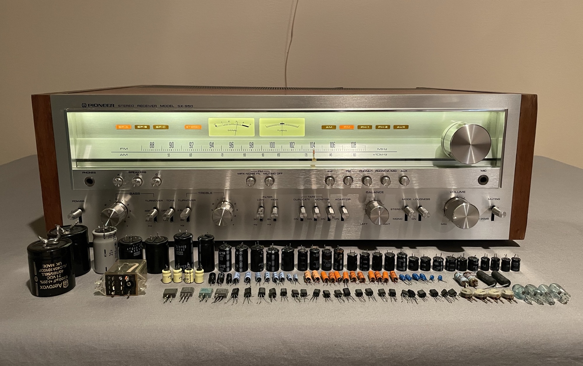
The final result can be seen in the photos below. The receiver looks great, works properly, and sounds awesome. Please watch a short demo video at the end of this post. Thank you for reading.

Pioneer SX-950 - after restoration

Pioneer SX-950_After Restoration

Pioneer SX-950_After Restoration_with parts

Demo video after repair & restoration