Unit: AM/FM Stereo Receiver
Manufacturer: Pioneer
Model: SX-737
SN: WD3976527S
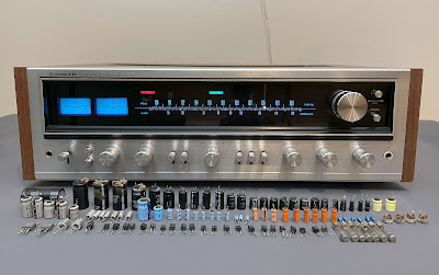
Today I'm showcasing a Pioneer SX-737 vintage receiver that came in for restoration. The SX-737 was manufactured from 1974 to 1976. It produces 35 watts per channel into 8 ohms with no more than 0.5% total harmonic distortion. The damping factor at 8 ohms is 40. The retail price in 1975 was $399.95 (Ref. Stereo Review, Stereo Directory 1975, page 45).
Power Supply Board (AWR-057-A)
The power supply board has 10 radial aluminum electrolytic capacitors (C8, C9, C10, C11, C12, C13, C16, C17, C18, C19) and one axial e-cap C7.
All radial e-caps were replaced with low-impedance Nichicon UPW/UPM caps. The original axial e-cap was replaced with a Vishay axial capacitor.
Test results on original capacitors removed from the power supply board:
C7: rated capacitance – 1000uF, measured – 1078uF, ESR – 0.32Ω, deviation: +8%
C8: rated capacitance – 330uF, measured – 300uF, ESR – 0.33Ω, deviation: -9%
C9: rated capacitance – 330uF, measured – 301uF, ESR – 0.16Ω, deviation: -9%
C10: rated capacitance – 330uF, measured – 331uF, ESR – 0.17Ω, deviation: 0%
C11: rated capacitance – 220uF, measured – 251uF, ESR – 1.53Ω, deviation: +14%
C12: rated capacitance – 220uF, measured – 245uF, ESR – 0.22Ω, deviation: +11%
C13: rated capacitance – 100uF, measured – 105uF, ESR – 0.27Ω, deviation: +5%
C16: rated capacitance – 220uF, measured – 258uF, ESR – 0.44Ω, deviation: +17%
C17: rated capacitance – 22uF, measured – 23uF, ESR – 0.84Ω, deviation: +5%
C18: rated capacitance – 100uF, measured – 111uF, ESR – 0.34Ω, deviation: +11%
C19: rated capacitance – 100uF, measured – 102uF, ESR – 0.22Ω, deviation: +2%
I also replaced all transistors on this board to improve the reliability of the power supply. Below is a list of original and replacement transistors that I have used. A fresh silicone thermal compound (Wakefield-Vette, 120 series) was applied between the new KSC2073TU transistor installed in position Q3 and the heat sink.
Q1: NPN, 2SD313 (original), replaced with a new Fairchild KSC2073TU
Q2: NPN, 2SC945 (original), replaced with a new Fairchild KSC2383YTA
Q3: NPN, 2SD313 (original), replaced with a new Fairchild KSC2073TU
Q4: NPN, 2SC945 (original), replaced with a new Fairchild KSC2383YTA
Power supply board - before and after
Protection Circuit Board (AWM-025-C)
The protection circuit board has 2 notorious sky-blue Sanyo capacitors (C1, C2) and 4 aluminum electrolytic capacitors (C3, C4, C5, C6).
The original Sanyo e-caps were replaced with high-quality film polyester Kemet capacitors. The remaining aluminum e-caps were replaced with low-impedance Nichicon UPW caps.
Test results on original capacitors removed from the protection circuit board:
C1: rated capacitance – 0.22uF, measured – 0.26uF, ESR – N/A, deviation: +18%
C2: rated capacitance – 0.22uF, measured – 0.19uF, ESR – N/A, deviation: -14%
C3: rated capacitance – 330uF, measured – 386uF, ESR – 0.77Ω, deviation: +17%
C4: rated capacitance – 330uF, measured – 405uF, ESR – 0.26Ω, deviation: +23%
C5: rated capacitance – 4.7uF, measured – 6.7uF, ESR – 1.88Ω, deviation: +43%
C6: rated capacitance – 100uF, measured – 116uF, ESR – 0.45Ω, deviation: +16%
The relay driver transistor Q7 suffers from the current spike every time the relay turns off. Eventually, it might fail due to severe degradation. I replaced the original 2SC1384 transistor with a new Fairchild KSC2690. The new transistor has the same pinout as the original one. Also, a fly-back safety diode (1N4004G) was added to the circuit to prevent potential output damage. The safety diode was soldered between pins 9 (anode, "+") and 10 (cathode, "-").
Protection circuit board - before and after
Speaker Protection Relay
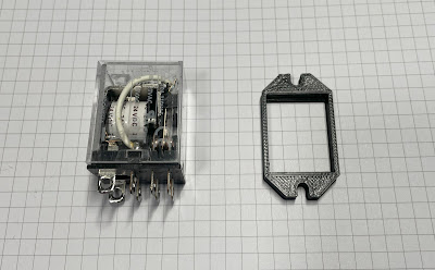
The original speaker protection relay in this receiver was previously replaced with a new Omron LY2-DC24 relay. However, this type of relay cannot be securely mounted on a chassis. As a result, it is quite loose and its contacts could potentially touch the metal chassis. To solve this problem, I used an aftermarket flange bracket to securely mount the new relay to the chassis.
Omron speaker protection relay - unmounted on a chassis
Omron speaker protection relay and aftermarket flange bracket
Flange bracket is attached to the relay
Power Amplifier Board (AWH-033-O)
The power amplifier board has 2 solid tantalum capacitors (C1, C2) installed in the input signal path and 6 aluminum electrolytic capacitors.
The original solid tantalum capacitors were replaced with modern low-leakage Nichicon UKL caps. The remaining aluminum e-caps were replaced with low-impedance Nichicon UPW caps.
Test results on original capacitors removed from the power amplifier board:
C1: rated capacitance – 4.7uF, measured – 4.8uF, ESR – 1.84Ω, deviation: +2%
C2: rated capacitance – 4.7uF, measured – 5.0uF, ESR – 1.67Ω, deviation: +6%
C7: rated capacitance – 220uF, measured – 201uF, ESR – 0.54Ω, deviation: -9%
C8: rated capacitance – 220uF, measured – 206uF, ESR – 0.66Ω, deviation: -6%
C9: rated capacitance – 47uF, measured – 53uF, ESR – 0.36Ω, deviation: +13%
C10: rated capacitance – 47uF, measured – 48uF, ESR – 0.78Ω, deviation: +2%
C19: rated capacitance – 22uF, measured – 27uF, ESR – 1.54Ω, deviation: +23%
C20: rated capacitance – 22uF, measured – 27uF, ESR – 1.62Ω, deviation: +23%
The first stage of the power amplifier circuit is a differential amplifier consisting of two amplifying transistors with a common emitter: Q1 & Q3 (left channel) and Q2 & Q4 (right channel). The original PNP transistor installed in these positions is 2SA726. This transistor is on my list of infamous transistors that are prone to failure. I replaced each pair of original 2SA726 transistors with a new close-matched pair of modern low-noise Fairchild KSA992 transistors. Each pair of new KSA992 transistors was carefully matched (within ~1%) by current gain and base-emitter voltage. Watch the pinout on replacement transistors. The original transistor is BCE and the new one is ECB.
Test results on original 2SA726 transistors
Q1 (left channel): hfe - 480, Vbe - 0.765V
Q3 (left channel): hfe - 477, Vbe - 0.765V
Q2 (right channel): hfe - 438, Vbe - 0.770V
Q4 (right channel): hfe - 440, Vbe - 0.767V
Test results on new KSA992 transistors
Q1 (left channel): hfe - 413, Vbe - 0.755V
Q3 (left channel): hfe - 413, Vbe - 0.758V
Q2 (right channel): hfe - 417, Vbe - 0.757V
Q4 (right channel): hfe - 416, Vbe - 0.757V
The original pre-driver transistor installed in positions Q5 and Q6 is 2SC1451. This transistor is also on my list of infamous transistors that are prone to failure. I replaced both transistors with a new Fairchild KSC3503 transistor.
Finally, the original trimming resistors were replaced with new Bourns potentiometers.
Power amplifier board - before and after
Equalizer Amplifier Board (AWF-011-0)
The equalizer amplifier board has 2 sky-blue Sanyo capacitors (C1, C2) installed in the input signal path, 2 low-leakage e-caps (C11, C12) installed in the output signal path, and 4 aluminum electrolytic capacitors (C7, C8, C17, C18).
The notorious Sanyo capacitors were replaced with high-quality film polyester WIMA caps. Note, that one of the original Sanyo capacitors (C2) has a very high ESR (>10Ω!). The original low-leakage e-caps were replaced with modern low-leakage Nichicon UKL caps. The remaining aluminum e-caps were replaced with low-impedance Nichicon UPW/UPM caps.
Test results on original capacitors removed from the equalizer amplifier board:
C1: rated capacitance – 1uF, measured – 1.2uF, ESR – 4.4Ω, deviation: +20%
C2: rated capacitance – 1uF, measured – 1.2uF, ESR – 10.2Ω, deviation: +20%
C7: rated capacitance – 330uF, measured – 393uF, ESR – 0.49Ω, deviation: +19%
C8: rated capacitance – 330uF, measured – 392uF, ESR – 0.16Ω, deviation: +19%
C11: rated capacitance – 3.3uF, measured – 4.1uF, ESR – 3.4Ω, deviation: +24%
C12: rated capacitance – 3.3uF, measured – 4.4uF, ESR – 3.6Ω, deviation: +33%
C17: rated capacitance – 100uF, measured – 112uF, ESR – 0.21Ω, deviation: +12%
C18: rated capacitance – 220uF, measured – 249uF, ESR – 0.32Ω, deviation: +34%
The original PNP transistors (Q1 and Q2) installed in the first stage are notorious 2SA725. The failure of this transistor usually results in a shot noise. I replaced both of them with a modern low-noise Fairchild KSA992. Watch the pinout on replacement transistors. The original transistor is BCE and the new one is ECB.
The original NPN transistors (Q3, Q4, Q5, and Q6) installed on this board are 2SC1313. These are also known as noisy/leaky transistors. I replaced them with a modern low-noise Fairchild KSA1845. Watch the pinout on replacement transistors. The original transistor is BCE and the new one is ECB.
Equalizer amplifier board - before and after
Microphone Amplifier Board (AWM-066-0)
The microphone amplifier board has one sky-blue Sanyo capacitor C3, one low-leakage e-cap C7, and 2 aluminum electrolytic capacitors C2 and C6.
Both notorious Sanyo and low-leakage capacitors were replaced with film polyester WIMA caps. The remaining aluminum e-caps were replaced with low-impedance Nichicon UPW caps.
Test results on original capacitors removed from the microphone amplifier board:
C2: rated capacitance – 220uF, measured – 238uF, ESR – 0.14Ω, deviation: +8%
C3: rated capacitance – 0.47uF, measured – 0.65uF, ESR – N/A, deviation: +38%
C6: rated capacitance – 220uF, measured – 267uF, ESR – 0.28Ω, deviation: +21%
C7: rated capacitance – 0.47uF, measured – 0.52uF, ESR – N/A, deviation: +11%
The original NPN transistor installed in positions Q1 and Q2 is 2SC1344. This transistor is on my list of infamous transistors that are prone to failure. I replaced both transistors with a modern low-noise Fairchild KSA1845. Watch the pinout on replacement transistors. The original transistor is BCE and the new one is ECB.
Microphone amplifier board - before and after
Control Amplifier Board (AWG-030-O)
The control amplifier board has 4 solid tantalum (C1, C2, C23, C24) and 6 low-leakage e-caps (C9, C10, C17, C18, C19, C20) installed in the signal path, and 5 aluminum electrolytic capacitors (C5, C6, C21, C22, C29).
Both original solid tantalum capacitors (C1 & C2) installed in the input signal path have rather high ESR. I replaced them with film polyester WIMA caps. The other solid tantalum and low-leakage capacitors were replaced with modern low-leakage Nichicon UKL caps. The remaining aluminum e-caps were replaced with low-impedance Nichicon UPW caps.
Test results on original capacitors removed from the control amplifier board:
C1: rated capacitance – 1uF, measured – 1uF, ESR – 7.4Ω, deviation: 0%
C2: rated capacitance – 1uF, measured – 1uF, ESR – 11.6Ω, deviation: 0%
C5: rated capacitance – 100uF, measured – 112uF, ESR – 0.38Ω, deviation: +12%
C6: rated capacitance – 100uF, measured – 115uF, ESR – 1.72Ω, deviation: +15%
C9: rated capacitance – 4.7uF, measured – 6.0uF, ESR – 3.8Ω, deviation: +28%
C10: rated capacitance – 4.7uF, measured – 6.4uF, ESR – 2.3Ω, deviation: +36%
C17: rated capacitance – 4.7uF, measured – 5.8uF, ESR – 4.4Ω, deviation: +23%
C18: rated capacitance – 4.7uF, measured – 5.8uF, ESR – 3.9Ω, deviation: +23%
C19: rated capacitance – 4.7uF, measured – 5.9uF, ESR – 4.1Ω, deviation: +26%
C20: rated capacitance – 4.7uF, measured – 6.1uF, ESR – 3.2Ω, deviation: +30%
C21: rated capacitance – 47uF, measured – 54uF, ESR – 0.78Ω, deviation: +15%
C22: rated capacitance – 47uF, measured – 56uF, ESR – 0.82Ω, deviation: +19%
C23: rated capacitance – 2.2uF, measured – 2.3uF, ESR – 2.8Ω, deviation: +5%
C24: rated capacitance – 2.2uF, measured – 2.2uF, ESR – 3.4Ω, deviation: 0%
C29: rated capacitance – 100uF, measured – 103uF, ESR – 0.18Ω, deviation: +3%
The original PNP transistors (Q1 and Q2) installed in the first stage are notorious 2SA726. I replaced both of them with a modern low-noise Fairchild KSA992. Watch the pinout on replacement transistors. The original transistor is BCE and the new one is ECB.
The original NPN transistor installed in positions Q3, Q4, Q5, and Q6 is prone to failure 2SC1344. I replaced both transistors with a modern low-noise Fairchild KSA1845. Watch the pinout on replacement transistors. The original transistor is BCE and the new one is ECB.
Control amplifier board - before and after
Switch & Volume Circuit Assembly (AWX-071-0)
This board has only one aluminum electrolytic capacitor C5. I replaced it with a low-impedance Nichicon UPW cap.
Tuner Assembly (AWE-043-A)
Usually, I do not service the tuner section unless there is a specific problem. But the tuner board in this model has a bunch of notorious sky-blue Sanyo capacitors that must be replaced. Also, this board has 2 notorious 2SA725 transistors installed in positions Q8 and Q9. These must be replaced as well.
The tuner board has 6 sky-blue Sanyo capacitors (C38, C39, C40, C49, C50, C66) and 9 aluminum electrolytic capacitors (C25, C27, C28, C33, C58, C59, C64, C67, C68).
All original Sanyo capacitors were replaced with high-quality film polyester capacitors: WIMA (C38, C39, C40, C49, C50) and Kemet (C66). Note, that one of the original Sanyo capacitors (C39) has a very high ESR (>10Ω!). Two original aluminum electrolytic capacitors C28 and C33 were also replaced with film polyester WIMA caps. The remaining aluminum e-caps were replaced with low-impedance Nichicon UPW/UPM caps.
Test results on original capacitors removed from the tuner assembly board:
C25: rated capacitance – 4.7uF, measured – 5.5uF, ESR – 2.2Ω, deviation: +17%
C27: rated capacitance – 10uF, measured – 13uF, ESR – 1.72Ω, deviation: +30%
C28: rated capacitance – 0.47uF, measured – 0.51uF, ESR – N/A, deviation: +9%
C33: rated capacitance – 1uF, measured – 1.1uF, ESR – 2.6Ω, deviation: +10%
C38: rated capacitance – 0.33uF, measured – 0.37uF, ESR – N/A, deviation: +12%
C39: rated capacitance – 1uF, measured – 1.2uF, ESR – 11.3Ω, deviation: +20%
C40: rated capacitance – 0.47uF, measured – 0.48uF, ESR – N/A, deviation: +2%
C49: rated capacitance – 0.47uF, measured – 0.48uF, ESR – N/A, deviation: +2%
C50: rated capacitance – 0.47uF, measured – 0.44uF, ESR – N/A, deviation: -6%
C58: rated capacitance – 4.7uF, measured – 5.6uF, ESR – 1.89Ω, deviation: +19%
C59: rated capacitance – 47uF, measured – 58uF, ESR – 0.72Ω, deviation: +23%
C64: rated capacitance – 10uF, measured – 13uF, ESR – 1.45Ω, deviation: +30%
C66: rated capacitance – 0.1uF, measured – 0.12uF, ESR – N/A, deviation: +20%
C67: rated capacitance – 220uF, measured – 235uF, ESR – 0.24Ω, deviation: +7%
C68: rated capacitance – 100uF, measured – 121uF, ESR – 0.38Ω, deviation: +21%
Two prone-to-failure 2SA725 transistors installed in positions Q8 and Q9 were replaced with modern low-noise Fairchild KSA992 transistors. Watch the pinout on replacement transistors. The original transistor is BCE and the new one is ECB.
Tuner assembly - before and after
Dial and Meter Lamps
The dial and meter lamps in this model are easily accessible. I replaced them with new warm white LED lamps.
DC offset and Bias Adjustments
Be aware, that the service manual has an error for DC offset and bias adjustments. The correct procedure is described below.
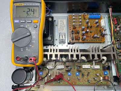
The DC offset on the left channel is measured between terminal 3 and the ground. On the right channel, it is measured between terminal 17 and the ground. The DC offset should be adjusted as close to zero volts as possible with the trimming resistors VR3 and VR4, respectively.
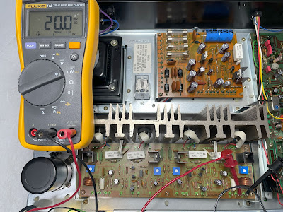
The Bias is measured across two emitter resistors R31 and R33 on each channel. So, the voltmeter should be connected between terminal 2 (+) and terminal 1 (-) on the left channel. On the right channel, the voltmeter should be connected between terminal 18 (+) and terminal 19 (-). The Bias should be adjusted to 20mV on each channel with the trimming resistors VR1 and VR2.
DC offset on the left and right channels after restoration
Bias on the left and right channels after restoration
Output Power Test
The final output power test was performed at the end of my restoration. The receiver was loaded with a low inductance 8Ω/100W dummy resistor for each channel. The oscilloscope was connected across the speaker terminals and a sine-wave signal of 1kHz was applied to the AUX jacks. The output sine-wave signal was perfectly symmetrical on both channels with no clipping up to 18.24 VRMS (left channel) and 18.41 VRMS (right channel). It corresponds to the output power of 41.6W on the left channel and 42.4W on the right channel.
Output power test
As usual, all the knobs and the front panel were gently cleaned in warm water with dish soap. All controls have been cleaned with DeoxIT 5% contact cleaner and lubricated with DeoxIT FaderLube 5% spray.
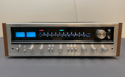
The final result can be seen in the photos below. The receiver looks and sounds great again. Please watch a short demo video at the end of this post. Thank you for reading.
Pioneer SX-737 - after restoration

_before%20servicing.jpg)
_after%20servicing.jpg)
_before%20servicing.jpg)
_after%20servicing.jpg)




_before%20servicing.jpg)
_after%20servicing.jpg)
_before%20servicing.jpg)
_after%20servicing.jpg)
_before%20servicing.jpg)
_after%20servicing.jpg)
_before%20servicing.jpg)
_after%20servicing.jpg)
_before%20servicing.jpg)
_after%20servicing.jpg)
_before%20servicing.jpg)
_after%20servicing.jpg)
