Home

Saturday, July 16, 2022

Marantz 1060 Stereo Integrated Amplifier Restoration

Unit: Stereo Integrated Amplifier
Manufacturer: Marantz
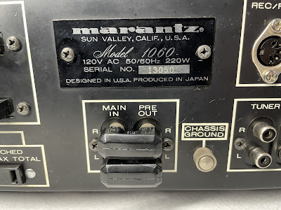
Model: 1060
SN: 13050

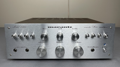
Today I'm showcasing one of the most well-known, respected, and popular integrated amplifiers of the 70's. This amplifier is one of the most valuable among collectors, and the price only gets higher over time. As many of you might guess, this is a Marantz Model 1060.

Marantz 1060 was manufactured from 1971 to 1978. It produces 30 watts per channel into 8 ohms with no more than 0.5% total harmonic distortion. The optional walnut veneer cabinet for this model is WC-10.

Marantz_1060_After Restoration

Power Supply Board (P800)

The power supply unit provides +35V DC (pin J806) to the phono amplifier and +27V DC (pin J807) to the tone & pre-amplifier board. 
 
Four electrolytic capacitors (C803, C804, C805, and C806) installed on this board were replaced with low impedance and high-reliability Nichicon UPW/UPM e-caps. The dried glue under each capacitor was carefully removed. The original e-caps were tested with an Atlas ESR70 capacitance meter. The capacitance of two of the four capacitors is outside the factory tolerance +/- 20%.

Test results on original capacitors removed from the power supply board:

C803: rated capacitance – 470uF, measured – 549uF, ESR – 0.01Ω, deviation: +17%
C804: rated capacitance – 100uF, measured – 161uF, ESR – 0.06Ω, deviation: +61%
C805: rated capacitance – 330uF, measured – 353uF, ESR – 0.02Ω, deviation: +7%
C806: rated capacitance – 100uF, measured – 154uF, ESR – 0.03Ω, deviation: +54%

The original semiconductor devices installed on this board were also replaced to improve the reliability of the power supply. The regulating transistor 2SC1318 installed in position H801 was replaced with a new Fairchild KSC2383YTA. Two diodes SIB-01-02 installed in positions H802 and H803 were upgraded to fast recovery rectifiers UF4005.

Power supply board - before and after

Marantz_1060_Power Supply (P800)_before servicing

Marantz_1060_Power Supply (P800)_after servicing

Tone & Pre-Amplifier Board (P400)

The tone & pre-amplifier board has eight low leakage capacitors (C403, C404, C407, C408, C410, C411, C412, C413), two bi-polar e-caps (C414, C415), and three aluminum electrolytic capacitors (C405, C406, C409). The original low leakage and two bi-polar e-caps were replaced with high-quality film polyester WIMA caps. The remaining aluminum e-caps were replaced with low impedance Nichicon UPW/UPM caps.

Test results on original capacitors removed from the tone & pre-amplifier board:

C403: rated capacitance – 1uF, measured – 1uF, ESR – 4.4Ω, deviation: 0%
C404: rated capacitance – 1uF, measured – 1uF, ESR – 4.2Ω, deviation: 0%
C405: rated capacitance – 10uF, measured – 10uF, ESR – 1.56Ω, deviation: 0%
C406: rated capacitance – 10uF, measured – 10uF, ESR – 1.63Ω, deviation: 0%
C407: rated capacitance – 3.3uF, measured – 3.5uF, ESR – 1.87, deviation: +6%
C408: rated capacitance – 3.3uF, measured – 3.4uF, ESR – 2.1Ω, deviation: +3%
C409: rated capacitance – 100uF, measured – 104uF, ESR – 0.09Ω, deviation: +4%
C410: rated capacitance – 3.3uF, measured – 3.5uF, ESR – 2.1Ω, deviation: +6%
C411: rated capacitance – 3.3uF, measured – 3.4uF, ESR – 2.6Ω, deviation: +3%
C412: rated capacitance – 0.47uF, measured – 0.48uF, ESR – N/A, deviation: +2%
C413: rated capacitance – 0.47uF, measured – 0.48uF, ESR – N/A, deviation: +2%
C414: rated capacitance – 1uF, measured – 1uF, ESR – 2.6Ω, deviation: 0%
C415: rated capacitance – 1uF, measured – 1uF, ESR – 2.8Ω, deviation: 0%

Four NPN transistors installed on this board are Toshiba 2SC1000. This transistor is known to get noisy over time. I replaced all 2SC1000 transistors with modern low-noise Fairchild KSC1845s. The new transistor has the same pinout as the original one.

According to the service manual, all PNP transistors in this circuit should be 2SA493. However, instead of the recommended 2SA493, the 2SA702 transistor was installed on this board. The failure modes of the 2SA702 transistor are not well documented, but they should be replaced as well. I installed new Fairchild KSA992 transistors instead of 2SA702s.

Tone & pre-amp board - before and after

Marantz_1060_Tone & Pre-Amp (P400)_before servicing

Marantz_1060_Tone & Pre-Amp (P400)_after servicing

Phono Amplifier Board (P900)

The phono amplifier board has four low leakage capacitors (C901, C902, C905, C906), and three aluminum electrolytic capacitors (C909, C910, C919). Two original low leakage e-caps (C901 & C902) were replaced with film polyester WIMA caps. The other two low leakage caps were replaced with modern low leakage Nichicon UKL caps. The remaining aluminum e-caps were replaced with low impedance Nichicon UPW/UPM caps.

Test results on original capacitors removed from the phono amplifier board:

C901: rated capacitance – 1uF, measured – 0.9uF, ESR – 4.2Ω, deviation: -10%
C902: rated capacitance – 1uF, measured – 1uF, ESR – 3.8Ω, deviation: 0%
C905: rated capacitance – 22uF, measured – 23uF, ESR – 0.31Ω, deviation: +5%
C906: rated capacitance – 22uF, measured – 23uF, ESR – 0.68Ω, deviation: +5%
C909: rated capacitance – 47uF, measured – 66uF, ESR – 0.32Ω, deviation: +40%
C910: rated capacitance – 47uF, measured – 57uF, ESR – 0.35Ω, deviation: +21%
C919: rated capacitance – 100uF, measured – 138uF, ESR – 0.12Ω, deviation: +38%

Also, this board utilizes two types of notoriously bad transistors: 2SC1000 and 2SC458. Both transistors are well-known troublemakers and get noisy over time. I replaced them with modern low-noise Fairchild KSC1845s. Two transistors H905 and H906 were gain matched within 1%. Watch the pinout on the replacement transistors. The original 2SC1000 transistor has the same pinout as a new KSC1845, i.e. ECB. However, the 2SC458 transistor has a BCE pinout.

Phono amplifier board  - before and after

Marantz_1060_Phono Amp (P900)_before servicing

Marantz_1060_Phono Amp (P900)_after servicing

Power Amplifier Board (P700)

The power amplifier board in this unit has been previously serviced by someone. And I must say that this work was done poorly. The low-quality electrolytic capacitors were installed in several positions. The soldering quality is quite poor and messy. The lead of one resistor was bent but not soldered to the PCB. Everything must be redone.

Bad soldering, one lead was not soldered to the PCB

Marantz_1060_Power Amp Board (P700)_bad soldering, one lead was not soldered

The power amplifier board has four low leakage e-caps (C701, C702, C711, C712) installed in the signal path, and eight aluminum electrolytic capacitors (C703, C704, C707 thru C710, C717, C718). I replaced two original low leakage e-caps C701 and C702 with film polyester WIMA caps. The other two low leakage e-caps (C711 and C712) were replaced with modern low leakage Nichicon UKL caps. The remaining aluminum e-caps were replaced with low impedance Nichicon UPW/UPM caps.

I tested all e-caps removed from this board with an Atlas ESR70 capacitance meter and the results are below. The measured capacitance of C709 is only 13uF (deviation from the rated capacitance is 72%!). Another e-cap C718 failed the test (open circuit/low capacitance).

Test results on original capacitors removed from the power amplifier board:

C701: rated capacitance – 1uF, measured – 1uF, ESR – 4.1Ω, deviation: 0%
C702: rated capacitance – 1uF, measured – 0.9uF, ESR – 4.3Ω, deviation: -10%
C703: rated capacitance – 47uF, measured – 45uF, ESR – 0.52Ω, deviation: -4%
C704: rated capacitance – 47uF, measured – 55uF, ESR – 0.1Ω, deviation: +17%
C707: rated capacitance – 47uF, measured – 48uF, ESR – 0.32Ω, deviation: +2%
C708: rated capacitance – 47uF, measured – 57uF, ESR – 0.28Ω, deviation: +21%
C709: rated capacitance – 47uF, measured – 13uF, ESR – 0.85Ω, deviation: -72%
C710: rated capacitance – 47uF, measured – 46uF, ESR – 0.26Ω, deviation: -2%
C711: rated capacitance – 10uF, measured – 11uF, ESR – 1.43Ω, deviation: +10%
C712: rated capacitance – 10uF, measured – 11uF, ESR – 1.16Ω, deviation: +10%
C717: rated capacitance – 22uF, measured – 22uF, ESR – 2.5Ω, deviation: 0%
C718: rated capacitance – 22uF, measured – open circuit/low capacitance

Both original pre-driver transistors (H701 & H702) were upgraded to the new Fairchild KSC945CYTA.

The original trimming resistors R723/R724 (100 kΩ, clipping level), and R729/R730 (470 Ω, Bias) were replaced with new Bourns potentiometers.

Power amplifier board - before and after

Marantz_1060_Power Amplifier Board (P700)_before servicing

Marantz_1060_Power Amp Board (P700)_after servicing

Power Transistors

Two power transistors from the left channel in this unit were previously replaced with Sylvania ECG280. The other two transistors from the right channel are original Marantz 2SC897D. I tested the power transistors with Atlas DCA55 semiconductor analyzer and all transistors are still good. However, I am not familiar with Sylvania power transistors and have doubts about their performance/quality. So, I decided to replace all four transistors with new ON Semiconductor MJ21194G's. The new transistors are specifically designed for high-power audio output and have excellent gain linearity. In addition, the total harmonic distortion measured on two matched pairs of MJ21194G transistors can be as low as 0.08% according to the datasheet. So, it is a perfect choice as a substitution transistor for the original 2SC897D. The new Mica pads and fresh thermal compound were applied between each power transistor and heat sink. The fresh thermal compound was also applied to the thermal tracking diodes H005 and H006.

Old power transistors (Sylvania ECG280 and Marantz 2SC897D)

Marantz_1060_Power Transistors

New power transistors are installed (ON Semiconductor MJ21194G)

Marantz_1060_New Power Transistors

Missing Pre-OUT/Main IN terminal

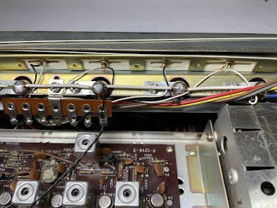
For some reason, the Pre-OUT/Main IN terminal as well as both jumper plugs were missing in this unit. Somebody who serviced this unit before removed it from the rear panel, cut out the wires, and bypassed the Pre-OUT/Main IN terminal directly to the power amplifier board. What a stupid solution! It looks ugly and disrespectful to this beautiful amplifier. 

I installed a new terminal from the old stock and rewired all connections according to the schematic. Two resistors (R007 & R008, 220 kΩ, 1/4 W) were also soldered between the input and ground following the schematic diagram.

Missing Pre-OUT/Main IN terminal and jumper plugs

Marantz_1060_Missing Pre-OUT-Main IN_Terminal and Jumper Plugs

New Pre-OUT/Main IN terminal and jumper plugs are installed

Marantz_1060_New Pre-OUT-Main IN_Terminal and Plugs

Power Amplifier Adjustment

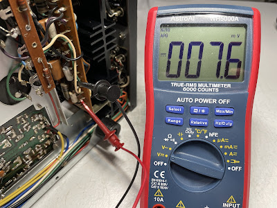
The Bias is measured across the emitter resistors R747 (jacks 713 & 715) and R748 (jacks 714 & 716). It was adjusted to ~7.5mV on each channel according to the service manual with trimming resistors R729 and R730.

The other two trimming resistors (R723 & R724) are used to adjust an equal and symmetrical clipping of the 1 kHz sine-wave signal.

Bias on the left and right channels after restoration

Marantz_1060_Bias_left channel

Marantz_1060_Bias_right channel

Output Power Test

The final output power test was performed at the end of my restoration. The amplifier was loaded with a low inductance 8Ω/100W dummy resistor for each channel. The oscilloscope was connected across the speaker terminals and a sine-wave signal of 1kHz was applied to the AUX jacks. The output sine-wave signal was perfectly symmetrical on both channels with no clipping up to 16.54 VRMS (left channel) and 16.48 VRMS (right channel). It corresponds to the output power of 34.2W on the left channel and 33.9W on the right channel.

Output power test

Marantz_1060_Output Power Test

As usual, all the knobs and the face plate were gently cleaned in warm water with dish soap. All controls have been cleaned with DeoxIT 5% contact cleaner and lubricated with DeoxIT FaderLube 5% spray.

The final result can be seen in the photos below. The amplifier looks brand new again and sounds awesome. Please watch a short demo video at the end of this post. Thank you for reading.

Marantz 1060 - before and after restoration, inside view

Marantz_1060_Inside View_before servicing

Marantz_1060_Inside View_after servicing

Marantz 1060 - after restoration

Marantz_1060_After Restoration

Marantz_1060_After Restoration_with parts

Demo video after repair & restoration

Sunday, July 3, 2022

Sansui 2000X Receiver Restoration

Unit: AM/FM Stereo Receiver
Manufacturer: Sansui
Model: 2000X
SN: 812030260

Today I'm showcasing a Sansui 2000X receiver that came in for restoration. It was manufactured from 1971 to 1973 and produces 39 watts per channel into 8 ohms with no more than 0.8% total harmonic distortion. The frequency response is pretty impressive from 20Hz to 40kHz. The damping factor is 24.

According to the Sansui database, this particular unit was manufactured in March 1972.

Sansui_2000X_After Restoration

Ripple Filter Block (F-1195-1)

This board has four aluminum electrolytic capacitors: C005, C006, C007, and C015. All of them were replaced with low impedance Nichicon UPW caps. The voltage rating was increased one step up on all capacitors.

Test results on original capacitors removed from the ripple filter block:

C005: rated capacitance – 220uF, measured – 248uF, ESR – 0.09Ω, deviation: +13%
C006: rated capacitance – 330uF, measured – 393uF, ESR – 0.08Ω, deviation: +19%
C007: rated capacitance – 330uF, measured – 376uF, ESR – 0.11Ω, deviation: +14%
C015: rated capacitance – 220uF, measured – 243uF, ESR – 0.08Ω, deviation: +11%

Ripple filter block - before and after

Sansui_2000X_Ripple Filter Block (F-1195-1)_before servicing

Sansui_2000X_Ripple Filter Block (F-1195-1)_after servicing

Rectifier Block (F-1197)

This board has only two aluminum electrolytic capacitors: C001 and C002. Both of them were replaced with low impedance UPW/UPM caps.

Test results on original capacitors removed from the rectifier block:

C001: rated capacitance – 220uF, measured – 218uF, ESR – 0.02Ω, deviation: -1%
C002: rated capacitance – 4.7uF, measured – 5.5uF, ESR – 1.11Ω, deviation: +17%

Rectifier block - before and after

Sansui_2000X_Rectifier Block (F-1197)_before servicing

Sansui_2000X_Rectifier Block (F-1197)_after servicing

Driver Amplifier Board (F-1180)

The driver amplifier board has twelve aluminum electrolytic capacitors (C802 thru C807, C812 thru C817). Two of them (C804 & C814) are installed in the signal path. I replaced them with high-quality film polyester WIMA caps to improve the signal-to-noise ratio. The remaining aluminum e-caps were replaced with low impedance Nichicon UPW caps.

Test results on original capacitors removed from the driver amplifier board:

C802: rated capacitance – 100uF, measured – 120uF, ESR – 0.26Ω, deviation: +20%
C803: rated capacitance – 220uF, measured – 255uF, ESR – 0.25Ω, deviation: +16%
C804: rated capacitance – 1uF, measured – 1.1uF, ESR – 2.4Ω, deviation: +10%
C805: rated capacitance – 33uF, measured – 36uF, ESR – 0.32Ω, deviation: +9%
C806: rated capacitance – 100uF, measured – 114uF, ESR – 0.22Ω, deviation: +14%
C807: rated capacitance – 10uF, measured – 13uF, ESR – 0.81Ω, deviation: +30%
C812: rated capacitance – 100uF, measured – 129uF, ESR – 0.24Ω, deviation: +29%
C813: rated capacitance – 220uF, measured – 249uF, ESR – 0.24Ω, deviation: +13%
C814: rated capacitance – 1uF, measured – 1uF, ESR – 3.6Ω, deviation: 0%
C815: rated capacitance – 33uF, measured – 36uF, ESR – 0.33Ω, deviation: +9%
C816: rated capacitance – 100uF, measured – 117uF, ESR – 0.21Ω, deviation: +17%
C817: rated capacitance – 10uF, measured – 14uF, ESR – 0.92Ω, deviation: +40%

Two NPN transistors (TR801 & TR806) installed on this board are the notorious 2SC458LG. This transistor is prone to noise and I replaced both 2SC458LG with new Fairchild KSC1845. The new KSC1845 is a low-noise AF amplifier and is commonly used to replace noisy 2SC458LG transistor. Watch the pinout on replacement transistors if you need to service this board. The original transistor is BCE and the new is ECB.

Driver amplifier board (F-1180) - before and after

Sansui_2000X_Driver Amp Board (F-1180)_before servicing

Sansui_2000X_Driver Amp Board (F-1180)_after servicing

Tone Control Board (F-1222-1)

The tone control board has four low leakage e-caps (C707, C715, C721, C729) installed in the signal path, two axial aluminum e-caps (C712, C726), and seven radial aluminum e-caps (C703, C704, C706, CC714, C718, C720, C728). The original low leakage capacitors were replaced with film polyester WIMA caps. Two axial e-caps were replaced with new axial Vishay (138 AML series) capacitors. And, the remaining aluminum e-caps were replaced with low impedance Nichicon UPW caps.

Test results on original capacitors removed from the tone control board:

C703: rated capacitance – 220uF, measured – 244uF, ESR – 0.15Ω, deviation: +11%
C704: rated capacitance – 33uF, measured – 37uF, ESR – 1.28Ω, deviation: +12%
C706: rated capacitance – 33uF, measured – 37uF, ESR – 0.76Ω, deviation: +12%
C707: rated capacitance – 1uF, measured – 1uF, ESR – 1.75Ω, deviation: 0%
C712: rated capacitance – 10uF, measured – 12uF, ESR – 1.21Ω, deviation: +20%
C714: rated capacitance – 47uF, measured – 61uF, ESR – 1.32Ω, deviation: +30%
C715: rated capacitance – 1uF, measured – 1uF, ESR – 2.6Ω, deviation: 0%
C718: rated capacitance – 33uF, measured – 36uF, ESR – 1.31Ω, deviation: +9%
C720: rated capacitance – 33uF, measured – 38uF, ESR – 0.77Ω, deviation: +15%
C721: rated capacitance – 1uF, measured – 1uF, ESR – 2.2Ω, deviation: 0%
C726: rated capacitance – 10uF, measured – 14uF, ESR – 1.06Ω, deviation: +40%
C728: rated capacitance – 47uF, measured – 68uF, ESR – 1.31Ω, deviation: +45%
C729: rated capacitance – 1uF, measured – 1uF, ESR – 2.6Ω, deviation: 0%

Six NPN transistors (TR701 thru TR706) installed on this board are the notorious 2SC458LG. I replaced them with a new Fairchild KSC1845. The new transistors were gain matched within 1%. Again, watch the pinout on replacement transistors if you need to service this board.

Tone control board - before and after

Sansui_2000X_Tone Control (F-1222-1)_before servicing

Sansui_2000X_Tone Control (F-1222-1)_after servicing

Equalizer Amplifier Board (F-1253)

The equalizer amplifier board has eleven aluminum electrolytic capacitors: C601, C603, C604, C606, C607, C611, C613, C614, C616, C617, and C626. Two of them (C601 & C611) are solid aluminum e-caps installed in the input signal path. I replaced them with film polyester WIMA caps. The other two capacitors (C607 & C617) installed in the output signal path are just ordinary aluminum e-caps. These were replaced with low leakage Nichicon UKL caps. The remaining aluminum capacitors were replaced with low impedance Nichicon UPW caps.

Test results on original capacitors removed from the equalizer amplifier board:

C601: rated capacitance – 1.5uF, measured – 1.7uF, ESR – 4.4Ω, deviation: +13%
C603: rated capacitance – 33uF, measured – 36uF, ESR – 1.32Ω, deviation: +9%
C604: rated capacitance – 33uF, measured – 35uF, ESR – 1.35Ω, deviation: +6%
C606: rated capacitance – 47uF, measured – 59uF, ESR – 1.36Ω, deviation: +26%
C607: rated capacitance – 10uF, measured – 13uF, ESR – 1.86Ω, deviation: +30%
C611: rated capacitance – 1.5uF, measured – 1.4uF, ESR – 2.6Ω, deviation: -7%
C613: rated capacitance – 33uF, measured – 36uF, ESR – 1.33Ω, deviation: +9%
C614: rated capacitance – 33uF, measured – 36uF, ESR – 1.38Ω, deviation: +9%
C616: rated capacitance – 47uF, measured – 56uF, ESR – 1.57Ω, deviation: +19%
C617: rated capacitance – 10uF, measured – 11uF, ESR – 2.3Ω, deviation: +10%
C626: rated capacitance – 100uF, measured – 122uF, ESR – 0.51Ω, deviation: +22%

Four NPN transistors installed on this board are prone to noise 2SC871. I replaced them with a new Fairchild KSC1845. The new transistors were gain matched within 1%. Watch the pinout on replacement transistors if you need to service this board. The original transistor is BCE and the new is ECB.

Equalizer amplifier board - before and after

Sansui_2000X_Equalizer Amplifier Board (F-1253)_before servicing

Sansui_2000X_Equalizer Amplifier Board (F-1253)_after servicing

AM Meter Block (F-1220-1)

The AM meter block has two aluminum electrolytic capacitors: C335 and C345. The C345 is soldered on the foil side between the wiper terminal and the ground. The original capacitor C335 was replaced with a low impedance Nichicon UPW cap. The original capacitor C345 was replaced with a film polyester WIMA cap.

Test results on original capacitors removed from the AM meter block:

C335: rated capacitance – 4.7uF, measured – 7.3uF, ESR – 1.82Ω, deviation: +55%
C345: rated capacitance – 1uF, measured – 1.1uF, ESR – 2.8Ω, deviation: +10%

AM meter block - before servicing

Sansui_2000X_AM Meter Block (F-1220-1)_before servicing

Sansui_2000X_AM Meter Block (F-1220-1)_foil side_before servicing

AM meter block - after servicing

Sansui_2000X_AM Meter Block (F-1220-1)_after servicing

Sansui_2000X_AM Meter Block (F-1220-1)_foil side_after servicing

Accessories Block (F-1254-1)

The accessories block has only two aluminum electrolytic capacitors: C739 and C740. It is possible to replace these capacitors without disassembling the board from the chassis. I replaced them with film polyester WIMA caps. Sorry, I didn't take a picture of this board.

Test results on original capacitors removed from the accessories block:

C739: rated capacitance – 0.47uF, measured – 0.45uF, ESR – N/A, deviation: -4%
C740: rated capacitance – 0.47uF, measured – 0.51uF, ESR – N/A, deviation: +9%

Dial and Meter Lamps

The dial and meter lamps in this unit were replaced with new incandescent lamps (6V, 0.25A, screw base). The dial lamps can be accessed from the front panel when the scale is removed.

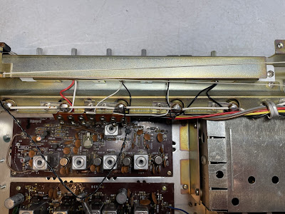
The stereo indicator and one function indicator lamp were blown out in this unit. I replaced them with new incandescent lamps as well. Access to these lamps is very limited and additional disassembling is required (at least the cover plate should be removed).

The cover plate removed to access the stereo indicator and function indicator lamps

Sansui_2000X_Cover plate removed

New Stereo and AUX indicator lamps were installed

Sansui_2000X_New lamps installed_Stereo and AUX

Idling Current and Symmetrical Clipping Adjustments

The idling current was adjusted to ~15mA on each channel according to the service manual. Two large trimming resistors (VR802 & VR804, 1kΩ each) are used for idling current adjustment.

Two small trimming resistors (VR801 & VR803, 200kΩ each) are used to adjust an equal clipping of the 1 kHz sine-wave signal.

Idling current on the left and right channels after restoration

Sansui_2000X_Idling Current_left channel

Sansui_2000X_Idling Current_right channel

Output Power Test

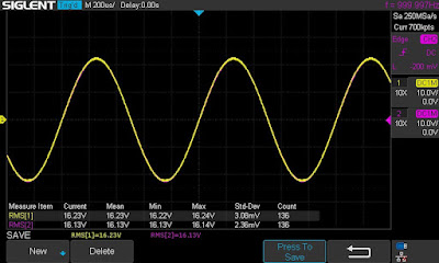
The final output power test was performed at the end of my restoration. The amplifier was loaded with a low inductance 8Ω/100W dummy resistor for each channel. The oscilloscope was connected across the speaker terminals and a sine-wave signal of 1kHz was applied to the AUX jacks. The output sine-wave signal was perfectly symmetrical on both channels with no clipping up to 16.23 VRMS (left channel) and 16.13 VRMS (right channel). It corresponds to the output power of  32.9W on the left channel and 32.5W on the right channel.

Output power test

Sansui_2000X_Output Power Test

As usual, all the knobs and the front panel were gently cleaned in warm water with dish soap. All controls have been cleaned with DeoxIT 5% contact cleaner and lubricated with DeoxIT FaderLube 5% spray. The wood case was stained with Howard's Restor-A-Finish.

The final result can be seen in the photos below. The receiver looks brand new again and sounds fantastic! Classic Sansui receiver from the 70's! Please watch a short demo video at the end of this post. Thank you for reading.

Sansui 2000X - after restoration

Sansui_2000X_After Restoration

Sansui_2000X_After Restoration_with parts

Demo video after repair & restoration