Unit: AM/FM Stereo Receiver
Manufacturer: Pioneer
Model: SX-828
SN: TE3718523
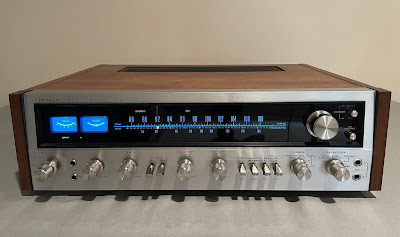
Today I'm showcasing a Pioneer SX-828 stereo receiver that came in for restoration. I restored another SX-828 a few months ago and one can read the restoration process in detail here: Pioneer SX-828 receiver restoration. However, the restoration I completed earlier on another SX-828 describes only servicing of two boards along with dial and meter lamps replacement. That was a customer request since he had a limited budget for restoring his receiver. In this post, I am going to describe the servicing of all boards in Pioneer SX-828 except a tuner section. Some information will probably duplicate my previous post but I will try to avoid it as much as possible.
Below are some photos I took during the restoration process, complete with comments and recommendations. This particular receiver came in with various electronic and mechanical issues. I will describe each of them in the corresponding section. I hope this post will be a good reference for everyone who has this receiver and wants to restore it to a factory spec. I usually don't make any modifications to the circuit design trying to stick with the original circuit topography. However, some particular electronic components I replaced in this unit will definitely improve the original sound quality. In general, the Pioneer SX-828 is a very well-built receiver but not the easiest to work on. However, it is always worth the effort.
According to the Pioneer database, this particular unit was manufactured in May 1973.
Initial Evaluation and Troubleshooting
As I mentioned earlier this particular receiver came in with various electronic and mechanical issues.
(a) The original STEREO and FM indicator lamps have been replaced in the past but it was done carelessly. I re-soldered the wires and insulate them with shrink tubing instead of electric tape.
(b) Also, all wires from the SPEAKER/POWER switch have been cut in the past, re-wired, and insulated by electric tape. I decided to re-work it to keep the receiver in good shape. To my surprise, almost all of them were not soldered at all and each connection was kind of loosened. I re-soldered all those wires and insulate them with shrink tubing to get a good and secure connection.
Wires from the SPEAKER/POWER switch - before and after
(c) The original dial pointer bulb burned out in this unit and I replaced it with a new incandescent lamp. This work requires a lot of patience and punctuality. It is very easy to break the thin plastic pointer during the lamp replacement. I used an X-ACTO #2 Knife and small pliers to release it from the metal case.
Dial pointer lamp - before and after
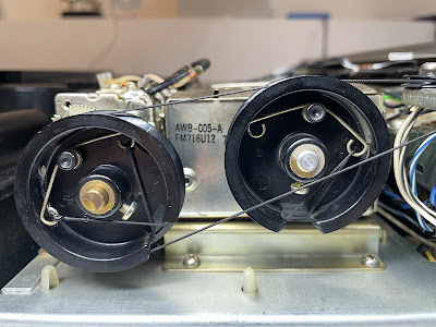
(d) Previously someone tried to re-string the dial cord in this receiver but did it wrong. As a result, the dial pointer was moving to the left when the tuning knob was rotating clockwise, and to the right when the tuning knob was rotating counterclockwise. I reworked it according to the instructions in the service manual. This procedure is quite simple and can be easily done on this model. Just carefully follow the instructions in the service manual and preferably use a new dial cord.
Dial cord is stringed incorrectly
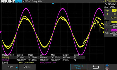
(e) Both channels in this receiver were cut out occasionally. And it was predominately at low volume. The BALANCE and VOLUME pots were very dirty and also contributed to the scratchy sound. The other switches (LOUDNESS, AUDIO MUTING, TAPE MONITOR, LOW and HIGH FILTER) had contaminated/oxidized contacts as well. I thoroughly cleaned all pots and switches with DeoxIT 5% contact cleaner and lubricated with DeoxIT FaderLube 5% spray. The scratchy sound has gone after that but it didn't solve a problem with channels occasionally cutting out. I decided to trace the input signal from AUX terminals through all boards down to the speaker's terminals to see if I can catch at which point the signal cuts out. So, I connected my function generator to the AUX terminals, applied a sine-wave signal of 1 kHz, and traced the input signal with my oscilloscope throughout all boards: INPUT SELECTOR, AF amplifier IN/OUT, Main amplifier IN/OUT, etc. At each testing point, I played with all switches and pots to see if they would distort or attenuate somehow the input signal. The signal was clear and without any distortion or attenuation until I reached the protection relay. The picture below shows the sine-wave signal detected at two testing points. The pink curve represents the signal measured at pin 9 of the protection relay (IN) and the yellow curve shows the signal detected at pin 5 (OUT). As one can see the sine-wave signal is highly distorted at pin 5 which means that most probably the relay's contacts are worn and don't provide a good contact anymore.
Original protection relay - the signal measured at pin 9 (pink curve, IN) and pin 5 (yellow curve, OUT)
I replaced the original relay with a new Omron (part # LY2F-DC24) and the signal was restored across the protection relay (see the picture below). The replacement relay has mounts and pins on opposite sides. I added the standoff supports to mount a new relay on the chassis.
Original protection relay
New Omron protection relay
Power Supply Board AWR-010-B
The power supply board AWR-010-B in Pioneer SX-828 is notorious for two transistors Q1 and Q3 running extremely hot (by design) under normal operating conditions. Each transistor is mounted on a heat sink but its size is too small to efficiently dissipate the excessive heat. Also, the metal oxide resistor R12 connecting the collector of Q1 to the collector of Q3 is running very hot as well. The rated power of R12 is 2W and its resistance is 330Ω. The voltage drop across R12 is usually measured from 20 to ~25V. The electrical power dissipated by this resistor can be calculated based on Ohm’s law: P = (V*V)/R = (25*25)/330 = 1.89W. And it is very close to the rated power of R12. The excessive heat coming from transistor Q3 and resistor R12 usually results in discoloration of PCB around these electronic components. In extreme cases, the PCB can be severely damaged.
I replaced transistors Q1 and Q3 with Fairchild MJE transistors due to better thermal characteristics in comparison to the original transistors. The resistor R12 was replaced with a flameproof 3W metal oxide resistor to improve its heat dissipation as well. Eight electrolytic capacitors C5 thru C10, C12 and C13 were replaced with low impedance and high-reliability Nichicon UPW caps. The maximum operating temperature of new electrolytic capacitors is +105C which is beneficial in power supply circuits. The original e-caps installed in vintage gears from the 70's have a maximum operating temperature of +85C. All original e-caps removed from this board were tested with Atlas ESR70 capacitance meter and results are below. All of them except e-cap C5 are still within a factory spec. However, the measured capacitance of C5 is almost 50% lower than its rated capacitance.
Test results on original capacitors removed from the power supply board:
C5: rated capacitance – 1000uF, measured – 506uF, ESR – 0.06Ω, deviation: -49%
C6: rated capacitance – 100uF, measured – 102uF, ESR – 0.12Ω, deviation: +2%
C7: rated capacitance – 100uF, measured – 100uF, ESR – 0.12Ω, deviation: 0%
C8: rated capacitance – 100uF, measured – 107uF, ESR – 0.12Ω, deviation: +7%
C9: rated capacitance – 100uF, measured – 105uF, ESR – 0.13Ω, deviation: +5%
C10: rated capacitance – 220uF, measured – 175uF, ESR – 0.26Ω, deviation: -20%
C12: rated capacitance – 220uF, measured – 262uF, ESR – 0.11Ω, deviation: +19%
C13: rated capacitance – 470uF, measured – 502uF, ESR – 0.13Ω, deviation: +7%
Power Supply board AWR-010-B - PCB discoloration due to excessive heat coming from Q3 and R12
Power Supply board AWR-010-B - after servicing
Protection Board AWM025-A
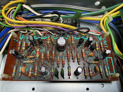
There are at least two versions of the protection board in Pioneer SX-828: W28-008 (the early version I believe) and AWM025 (the later version). This particular unit has a later version. The later version has two notorious sky-blue Sanyo e-caps C1 and C2 (0.22uF/10V) installed instead of Mylar capacitors (0.056uF/50V). The sky blue Sanyo e-caps have a bad reputation to get electrically leaky over time and eventually fail shorted. They were used in most Pioneer gears in the early 70's. I replaced them with high-quality film polyester Kemet caps. Also, in the later version two e-caps C3 and C4 were upgraded from 220uF/10V to 330uF/6.3V. These were replaced with low impedance Nichicon UPW caps. The e-cap C6 was also replaced with the Nichicon UPW cap. Another modification in the AWM025 protection circuit in comparison to W28-008 is the additional electrolytic capacitor C5 (4.7uF/25V). I replaced it with a Nichicon UPW cap as well.
Test results on original capacitors removed from the protection board:
C1: rated capacitance – 0.22uF, measured – 0.29uF, ESR – N/A, deviation: +32%
C2: rated capacitance – 0.22uF, measured – 0.28uF, ESR – N/A, deviation: +27%
C3: rated capacitance – 330uF, measured – 390uF, ESR – 0.08Ω, deviation: +18%
C4: rated capacitance – 330uF, measured – 392uF, ESR – 0.06Ω, deviation: +19%
C5: rated capacitance – 4.7uF, measured – 6.1uF, ESR – 1.1Ω, deviation: +30%
C6: rated capacitance – 100uF, measured – 108uF, ESR – 0.18Ω, deviation: +8%
Protection board AWM025-A - before and after
Head Amplifier Board W21-002-B
The head amplifier board W21-002-B has six NPN transistors Q1 thru Q6. According to the service manual, either 2SC871 or 2SC458 transistors can be installed. This particular unit has the 2SC458 transistors installed. This transistor gets very noisy over time. I replaced each 2SC458 transistor with a modern low noise Fairchild KSC1845. All new transistors were carefully matched by current gain and base-emitter voltage within 1%. Watch the pinout on replacement transistors while servicing this board. The original transistor is BCE and the new one is ECB.
Seven aluminum electrolytic capacitors (C1 thru C6 and C15) are installed on this board. Four of them C1/C2, C5/C6 are installed in the signal path. For some reason, Pioneer installed just ordinary aluminum e-caps in these positions. I replaced them with low leakage Nichicon UKL caps to improve the signal-to-noise ratio. The remaining e-caps C3/C4 and C15 were replaced with low impedance Nichicon UPW caps. All original e-caps removed from the head amplifier board were tested and the results are below. Most of them are outside of +/- 20% factory capacitance tolerance.
Test results on original capacitors removed from the head amplifier board:
C1: rated capacitance – 22uF, measured – 27uF, ESR – 0.46Ω, deviation: +23%
C2: rated capacitance – 22uF, measured – 29uF, ESR – 0.52Ω, deviation: +32%
C3: rated capacitance – 4.7uF, measured – 5.9uF, ESR – 1.23Ω, deviation: +26%
C4: rated capacitance – 4.7uF, measured – 6.0uF, ESR – 1.16Ω, deviation: +28%
C5: rated capacitance – 10uF, measured – 13uF, ESR – 0.47Ω, deviation: +30%
C6: rated capacitance – 10uF, measured – 12uF, ESR – 0.53Ω, deviation: +20%
C15: rated capacitance – 220uF, measured – 259uF, ESR – 0.02Ω, deviation: +18%
Head Amplifier board W21-002-B - before and after
AF Amp Board AWK-012-B
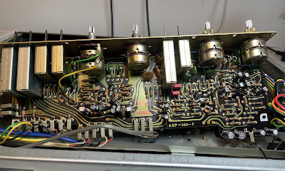
The SX-828 receiver is not the easiest one for servicing. The major problem is an AF amplifier board. This is a double solder PCB and requires a lot of patience while unsoldering and soldering the electronic components. It is very easy to overheat and damage it. So, pay close attention to this board while servicing it.
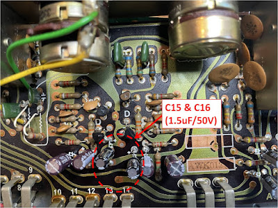
Seems like this board has been serviced in the past. Two coupling capacitors C37 and C38 are supposed to be at 1uF/25V but have been replaced with 0.68uF/50V e-caps. I replaced them with high-quality film polyester WIMA MKS2 caps, 1uF/50V. Another pair of coupling capacitors in question are C15 and C16. They are supposed to be at 1.5uF/25V but one of them C15 is at 3.3uF/25V while the C16 is 1.5uF/25V. In addition, these are two different types of e-caps. I tested the e-caps C15 and C16 with an Atlas ESR70 capacitance meter and the ESR of e-cap C16 is 12.8Ω! The ESR of e-cap C15 is 2.4Ω (see the test results for all e-caps removed from this board below). I replaced the e-caps C15 and C16 with low leakage Nichicon UKL caps, 1.5uF/50V. The remaining six coupling capacitors C25/C26, C31/C32, C45/C46 were also replaced with low leakage Nichicon UKL caps. The last ten aluminum e-caps on this board are C11 thru C14, C27 thru C30, C43, and C44. I replaced them with low impedance Nichicon UPW caps.
AF Amplifier board AWK-012-B - before servicing
AF Amplifier board AWK-012-B - blue e-caps C37 & C38 are supposed to be 1uF/25V
AF Amplifier board AWK-012-B - C37 & C38 replaced with film polyester WIMA MKS2 caps
AF Amplifier board AWK-012-B - e-cap C15 has an incorrect capacitance rating
AF Amplifier board AWK-012-B - C15 & C16 replaced with low leakage Nichicon UKL caps
Test results on original capacitors removed from the AF amplifier board:
C11: rated capacitance – 47uF, measured – 57uF, ESR – 0.45Ω, deviation: +21%
C12: rated capacitance – 47uF, measured – 58uF, ESR – 0.48Ω, deviation: +23%
C13: rated capacitance – 47uF, measured – 50uF, ESR – 0.16Ω, deviation: +6%
C14: rated capacitance – 47uF, measured – 49uF, ESR – 0.18Ω, deviation: +4%
C15: rated capacitance – 1.5uF, measured – 3.3uF, ESR – 2.4Ω, deviation: N/A (wrong cap)
C16: rated capacitance – 1.5uF, measured – 1.5uF, ESR – 12.8Ω, deviation: 0% (very high ESR!)
C25: rated capacitance – 3.3uF, measured – 3.3uF, ESR – 3.0Ω, deviation: 0%
C26: rated capacitance – 3.3uF, measured – 3.5uF, ESR – 1.8Ω, deviation: +6%
C27: rated capacitance – 100uF, measured – 126uF, ESR – 0.36Ω, deviation: +26%
C28: rated capacitance – 100uF, measured – 125uF, ESR – 0.26Ω, deviation: +25%
C29: rated capacitance – 47uF, measured – 50uF, ESR – 0.12Ω, deviation: +6%
C30: rated capacitance – 47uF, measured – 50uF, ESR – 0.11Ω, deviation: +6%
C31: rated capacitance – 2.2uF, measured – 2.4uF, ESR – 2.2Ω, deviation: +9%
C32: rated capacitance – 2.2uF, measured – 2.9uF, ESR – 2.0Ω, deviation: +32%
C37: rated capacitance – 1uF, measured – 0.67uF, ESR – N/A, deviation: N/A (wrong cap)
C38: rated capacitance – 1uF, measured – 0.72uF, ESR – N/A, deviation: N/A (wrong cap)
C43: rated capacitance – 100uF, measured – 94uF, ESR – 0.08Ω, deviation: -6%
C44: rated capacitance – 100uF, measured – 93uF, ESR – 0.08Ω, deviation: -7%
C45: rated capacitance – 3.3uF, measured – 3.3uF, ESR – 2.2Ω, deviation: 0%
C46: rated capacitance – 3.3uF, measured – 3.7uF, ESR – 3.6Ω, deviation: +12%
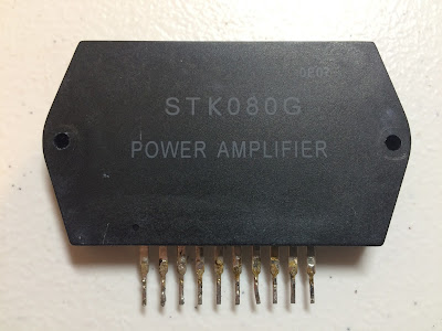
Four NPN transistors Q5 thru Q8 installed on this board are 2SC1312. I replaced them with modern low noise Fairchild KSC1845. Watch the pinout on replacement transistors. The original transistor is BCE and the new one is ECB. I also replaced two PNP transistors Q3 and Q4 with modern low noise Fairchild KSA992. The original PNP transistors are 2SA725 and they become very noisy over time.
AF Amplifier board AWK-012-B - after servicing
Main Amplifier Board AWH-010-D
The main amplifier board AWH-010-D has eight electrolytic capacitors C1, C2, C5, C6, C9 thru C12. Two of them C1 and C2 are installed in the signal path. However, for some reason, Pioneer installed just ordinary aluminum e-caps in these positions. I replaced them with high-quality film polyester WIMA MKS2 caps to improve the signal-to-noise ratio. The remaining six aluminum e-caps were replaced with low impedance Nichicon UPW/UPM caps. As can be seen from the test results six out of eight e-caps on this board are out of factory spec.
Test results on original capacitors removed from main amplifier board:
C1: rated capacitance – 1uF, measured – 1uF, ESR – 4.4Ω, deviation: 0%
C2: rated capacitance – 1uF, measured – 1uF, ESR – 5.4Ω, deviation: 0%
C5: rated capacitance – 22uF, measured – 28uF, ESR – 1.1Ω, deviation: +27%
C6: rated capacitance – 22uF, measured – 27uF, ESR – 1.1Ω, deviation: +23%
C9: rated capacitance – 220uF, measured – 328uF, ESR – 0.11Ω, deviation: +49%
C10: rated capacitance – 220uF, measured – 284uF, ESR – 0.06Ω, deviation: +29%
C11: rated capacitance – 100uF, measured – 125uF, ESR – 0.04Ω, deviation: +25%
C12: rated capacitance – 100uF, measured – 122uF, ESR – 0.06Ω, deviation: +22%
The first stage of the main amplifier circuit is a differential pair amplifier consisting of two amplifying transistors with a common emitter: Q1/Q3 (left channel) and Q2/Q4 (right channel). The original PNP transistors installed in these positions are notorious 2SA726. They get very noisy over time. I replaced them with modern Fairchild KSA992 transistors. Each pair of KSA992 transistors was carefully matched by current gain and base-emitter voltage before installation. Watch the pinout on replacement transistors. The original transistor is BCE and the new one is ECB.
Four NPN transistors Q5 thru Q8 installed on the main amplifier board are Sony 2SC1124. The current gain in the 2SC1124 transistor degrades with age. The modern substitution is a Fairchild KSC2690A transistor. I replaced the original Sony transistors with KSC2690A to prevent any issues in the future. Watch the pinout on replacement transistors. The original transistor is EBC and the new one is ECB.
Main Amplifier board AWH-010-D - before and after
Dial and Indicator Lamps
Five original dial bulbs in this unit were replaced with warm white LED lamps to maintain the original look and decrease heat. I also replaced two original bulbs behind the signal strength and FM tuning meters with warm white LED lamps. This process was described earlier in my previous post on servicing another SX-828 and can be found here: Pioneer SX-828 receiver restoration.
DC offset and Bias Adjustments
At the end of my restoration, I checked and adjusted the DC offset and Bias on the main amplifier unit. For some reason, this procedure is not described in the original manual but it is pretty much straightforward.
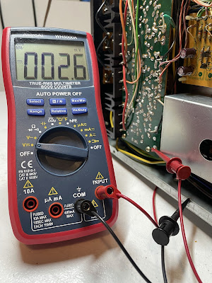
The DC offset is measured between pin 7 and ground on the left channel, and between pin 8 and ground on the right channel. It should be adjusted as close to zero volts as possible with the trimming resistors VR1 and VR2, respectively. To access these trimming resistors the protection shield covering the MC transformer socket should be removed.
The bias is measured across two emitter resistors. These are 5W wire wound resistors with rated resistance of 0.5Ω. The voltage drop across resistors R43 and R45 should be adjusted to ~20mV DC with the trimming resistor VR3 (the DC voltmeter is connected between pins 11 and 17). This is a bias on the left channel. And on the right channel, the voltage drop across resistors R44 and R46 should be adjusted to ~20mV DC with the trimming resistor VR4 (the DC voltmeter is connected between pins 12 and 18). To access these trimming resistors the protection shield covering the heat sink should be removed.
DC offset on the left and right channel after restoration
Bias on the left and right channel after restoration
Output Power Test
The output power test was conducted at the end of the restoration. Two low inductance 8Ω/100W resistors connected across each speaker terminal were used as a dummy load. The output sine-wave signal was perfectly symmetrical on both channels with no clipping up to 22.13 VRMS (left channel) and 22.67 VRMS (right channel). The output power on each channel can be calculated based on the following formula: P = (VRMS x VRMS)/8. The max output power (before clipping) is 61.2W on the left channel and 64.2W on the right channel. This is very close to the factory specification for this model. A very small difference observed between the left and right channels is due to imperfection/aging of the balance potentiometer. But that is still not too bad for a vintage gear manufactured almost half a century ago!
Output power test - still very close to factory specification
Pioneer SX-828 - after restoration
Demo video after repair & restoration


