Home

Sunday, March 21, 2021

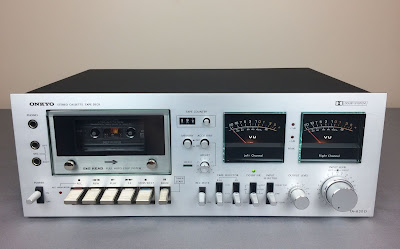
Onkyo TA-630D Cassette Deck Restoration

Unit: Stereo Cassette Tape Deck
Manufacturer: Onkyo
Model: TA-630D
SN: 10062943

I bought this cassette tape deck about two years ago from the original owner for just $25. The deck is in excellent cosmetic condition and there are only two almost invisible minor scratches on the faceplate. The owner told me that the last time he played the music on this deck was at least ten years ago. We met in a public place and I was not able to check whether it is working or not. But it was still a great deal since he wanted just $25 for it! I usually don't buy or restore vintage tape recorders because they often have problems with the transport mechanism, which I am not an expert in. But this tape deck was cheap, almost in perfect cosmetic condition, and most importantly for me, it has two large black VU meters! I am in love with vintage gears having VU meters. So, I bought it hoping to restore and keep it in my personal collection.

Onkyo TA-630D_After restoration_01

The Onkyo TA-630D is a stereo cassette deck with Dolby B noise reduction. It has 2 heads, belt-driven single-capstan transport, manual tape type selection handling normal, chrome and ferro-chrome tapes with additional manual equalization selection, and two large analog needle meters. The frequency response is from 30Hz to 18kHz on ferro-chrome tape and the signal to noise ratio is 68dB. It was manufactured from 1978 to 1980 with a list price of $350.

Belt Replacement

When I removed the top cover to check this unit inside I immediately noticed that we have a big problem here. The flat belt (Motor-Flywheel) and square-cut belt (Motor-pulley) have degraded so badly over time that both turned into sticky mush. Well, it looks like it wouldn't be an easy project. I checked online to get some guidance on how to replace these belts on this unit but with no success. There are just a few videos posted on YouTube about servicing Onkyo TA-630D but without good instructions for belt replacement. The service manual is also not very helpful for the belt replacement process. So, I decided to replace both belts based on my knowledge and experience with other cassette decks I restored before.

Further investigation revealed that this is definitely not a service-friendly cassette deck. I didn't find a way to replace two belts without disassembling and removing the metal bracket holding the motor and flywheel. Therefore, I initially removed the motor to clean its pulley from the sticky mush. This was an easy step but took some time to thoroughly clean the motor pulley from this messy stuff.

Sticky mush on the motor pulley from the old belt

Onkyo TA-630D_Sticky mush on motor pulley_01

Onkyo TA-630D_Sticky mush on motor pulley_02

Then, I tried to remove the sticky mush from the flywheel as much as possible before removing the metal bracket. I used a lot of Q-tips and isopropyl alcohol for that job.

Onkyo TA-630D_Sticky mush on flywheel

Eventually, I unscrew four small screws, removed the metal bracket, and pulled out the flywheel. I recommend paying attention to this step and taking a lot of pictures. Don't lose the poly washer and tension spring from the flywheel!

Metal bracket holding the motor and flywheel

Onkyo TA-630D_Metal bracket holding the motor and flywheel

Metal bracket and flywheel removed

Onkyo TA-630D_Metal bracket removed

I removed the residue of the old belt from all pulleys and cleaned them with isopropyl alcohol. The old lithium grease on most metal levers was mostly dried out. I removed this grease from all parts as much as I could and applied a new white lithium grease. The FF key on this unit was stuck but eventually came free with a little extra effort. I exercised all keys to make sure that the new grease penetrated between each lever and everything works smoothly.

The new flat belt (Motor-Flywheel) was installed in two steps. First of all, I installed a flywheel back and put a new flat belt on it. Then I installed the metal bracket trying not to damage a new flat belt and secured it with four screws. This step is the most critical one because the working space is really very limited here and a new belt tends to come off from the flywheel. So, take your time and don't rush at this step. When the metal bracket was successfully installed I mounted the motor on it and secured it with two screws. Then, using a pair of tweezers I was able to hang the belt to the motor pin.

A new flat belt (Motor-Flywheel) installed

Onkyo TA-630D_New flat motor belt installed

A new square cut belt (Motor-pulley) is fairly easy to install now since everything is mostly assembled. Double check the service manual to figure out how this belt should be installed. I used a pair of tweezers and with some patience was able to hang this belt as well.

A new square cut belt (Motor-pulley) installed

Onkyo TA-630D_New square cut belt installed

Onkyo TA-630D_New square cut belt installed_02

Cassette chassis assembled - back side

Onkyo TA-630D_Cassette chassis assembled

The last belt to replace is a counter belt. To access this belt one should remove the cassette door, cassette case, and cassette case plate. I didn't have any trouble removing these parts since the design is rather simple and it was intuitively clear what to do at each step.

Cassette door, case, and plate removed

Onkyo TA-630D_Cassette door, case and plate removed

Surprisingly but this belt survived and was still in pretty good condition. I vacuumed the deck chassis, cleaned the capstan, pinch roller, and both heads with isopropyl alcohol. Then applied a new white lithium grease to the rubbing metal parts and installed a new counter belt.

Clean chassis with new counter belt installed

Onkyo TA-630D_Clean chassis with new counter belt installed

For reference, I used the following belts in Onkyo TA-630D (Russel Industries, Inc. Cross-reference manual):
Flat belt (Motor-Flywheel) - FRZ7.5
Square cut belt (Motor-pulley) - SCQ8.2
Counter belt - SCY7.0

VU Meter Lamps

The lamp in the right channel VU meter has burned out and I decided to replace it with a new axial lamp. The meter is attached to the metal plate with double-sided tape. I used an X-ACTO #2 Knife to separate the meter from the metal plate. Pay attention to this step and don't apply too much force trying to separate it from the metal plate. Instead, try to carefully trim the double side tape with a proper knife/blade. The meter can be easily damaged due to extensive stress.

The lens is attached to the meter body with transparent tape which is not so easy to recognize at a first glance. I peeled off part of this transparent tape from the sides and carefully separated the lens from the meter body. According to the service manual, the original VU meter lamp is an axial 6.3V/100mA lamp. I replaced it with a new axial 6V/100mA lamp. The original lamp is a frosted bulb with a green tint whereas a new one is clear glass. I didn't find a suitable material to replicate the original green filter. The obvious option would be a green transparent tape wrapped around the lamp. But in that case, the tape would suffer from the extensive heat. So, I decided to leave it alone but also replace the original axial lamp from the left VU meter. At least both VU meters would match each other. Please leave a comment under this post if you have a better solution for a green filter.

VU Meters - the axial lamp in the right meter is burned out

Onkyo TA-630D_VU Meters_Original axial lamps

Each VU meter is attached to the metal plate with a double-sided tape

Onkyo TA-630D_VU Meters_Attached to the metal plate

Transparent tape on the sides of the VU meter lens

Onkyo TA-630D_VU Meters_Lens

Right VU meter - burned axial lamp

Onkyo TA-630D_Right VU Meter_Burned axial lamp

Right VU meter - new axial lamp installed

Onkyo TA-630D_Right VU Meter_New axial lamp

VU meters with new axial lamps

Onkyo TA-630D_New axial lamps in VU meters

I cleaned all the knobs and the faceplate in warm water with dish soap. All pots and switches have been cleaned with DeoxIT 5% contact cleaner and lubricated with DeoxIT FaderLube 5% spray.

The final result can be seen in the photos below. The transport mechanism is working properly again, all levers move smoothly and I am enjoying how it looks and plays music. Thank you for reading.

Onkyo TA-630D - after restoration

Onkyo TA-630D_After restoration_01

Onkyo TA-630D_After restoration_02

Saturday, March 6, 2021

Fisher 202 Receiver Restoration

Unit: AM/FM Stereo Receiver
Manufacturer: Fisher
Model: 202
SN: 22247

Another Fisher receiver (Futura series, model 202) came in for restoration. I restored exactly the same model a few months ago and one can read the restoration process in detail here: Fisher 202 receiver restoration. So, this post will be shorter than usual but I want to document what was done on this unit for future references. I hope it will be a good addition to my previous post about the Fisher 202 restoration.

Fisher 202_After restoration

Before I powered up this little receiver I checked the fuses on the back side to make sure that all of them have a correct rated current. There are three fuses on the back side: the main 2A slow blow fuse to protect the unit and two 2.5A slow blow fuses to protect the left and right channels. The fuse protecting the left channel was blown but someone bypassed it with a small piece of aluminum foil (!). Well, I was not surprised since you never know what can be found in these old units... Anyway, I replaced the blown fuse with a new one and powered the receiver up using my Dim Bulb Tester (DBT). The light bulb flashed for a second on bright and then dimmed out almost completely. So, this unit has no short circuit.

Blown fuse - bypassed with a small piece of aluminum foil

Fisher 202_Blown fuse bypassed with foil_01

Fisher 202_Blown fuse bypassed with foil_02

Power Amplifier Board

The Fisher 202 has two driver boards. These boards are very easy to service once removed from the slot. I didn't find any signs of overheating on these boards. All transistors and diodes have been tested and no bad components were found. So, I replaced only electrolytic capacitors. The original e-cap C01 installed in the signal path has a relatively high equivalent series resistance (ESR) of 2.6Ω (left channel) and 2.2Ω (right channel). I replaced it with a low leakage Nichicon UKL cap. The ESR of a new e-cap is only 1.5Ω which is lower in comparison to the original one. The lower ESR is always better, especially for e-caps installed in the signal path. The remaining three e-caps C02, C03, and C04 were replaced with low impedance and high-reliability Nichicon UPW capacitors. All original e-caps removed from the power amplifier board were tested with Atlas ESR70 capacitance meter and the results are below.

Test results on original capacitors removed from the power amplifier board:

C01-L: rated capacitance – 1uF, measured – 1.44uF, ESR – 2.6Ω, deviation: +44%
C01-R: rated capacitance – 1uF, measured – 1.36uF, ESR – 2.2Ω, deviation: +36%
C02-L: rated capacitance – 100uF, measured – 131uF, ESR – 0.05Ω, deviation: +31%
C02-R: rated capacitance – 100uF, measured – 131uF, ESR – 0.06Ω, deviation: +31%
C03-L: rated capacitance – 220uF, measured – 266uF, ESR – 0.15Ω, deviation: +21%
C03-R: rated capacitance – 220uF, measured – 270uF, ESR – 0.15Ω, deviation: +23%
C04-L: rated capacitance – 47uF, measured – 85uF, ESR – 0.19Ω, deviation: +81%
C04-R: rated capacitance – 47uF, measured – 77uF, ESR – 0.22Ω, deviation: +64%

Left and right driver boards - after servicing

Fisher 202_Power amp_After servicing

Power Transistors

The original Hitachi power transistors 2SC1030 were removed, cleaned, and tested with Atlas DCA55 semiconductor analyzer. According to the datasheet, the DC current gain measured in each transistor was in spec. However, it should be noted that Atlas DCA55 semiconductor analyzer provides the accurate reading for DC current gain only on low-power transistors. A high-power transistor requires a much higher collector current and collector-emitter voltage to accurately measure its current gain. However, it is still a very useful device for comparing transistors of a similar type for the purposes of gain matching or fault-finding.

I replaced the old thermal pads with new Mica ones and refreshed the thermal compound.

Original power transistors with new pads and thermal compound

Fisher 202_Power transistors_After servicing

Power Supply Board

The power supply board has three electrolytic capacitors C01, C02, and C03. These were replaced with low impedance Nichicon UPW caps. The new e-caps have a maximum operating temperature of +105C which is a beneficiary in power supply circuits. The original e-caps installed in vintage gears from the 70's have a maximum operating temperature of +85C. All original e-caps removed from the power supply board were tested and the results are below. The ESR of the original e-cap C03 is elevated. The new e-cap installed instead of C03 has a lower ESR of 0.15Ω.

Test results on original capacitors removed from the power supply board:

C01: rated capacitance – 100uF, measured – 134uF, ESR – 0.09Ω, deviation: +34%
C02: rated capacitance – 100uF, measured – 132uF, ESR – 0.07Ω, deviation: +32%
C03: rated capacitance – 220uF, measured – 368uF, ESR – 0.32Ω, deviation: +67%

Power supply board - before and after

Fisher 202_Power supply_Before servicing

Fisher 202_Power supply_After servicing

Pre-amplifier Board

I replaced all electrolytic capacitors on this board. The e-caps C1 and C2 installed in the signal path were replaced with low leakage Nichicon UKL caps. The original e-cap C1 installed in the right channel has a very high ESR in comparison to C2 in the left channel. The ESR of the Nichicon UKL capacitor is about 1.80Ω. The low ESR is critical for e-caps installed in the signal path. The remaining e-caps were replaced with low impedance Nichicon UPW/UPM caps.

Test results on original capacitors removed from Pre-amplifier board:

C1: rated capacitance – 10uF, measured – 12uF, ESR – 11.6Ω, deviation: +20%
C2: rated capacitance – 10uF, measured – 15uF, ESR – 1.84Ω, deviation: +50%
C9: rated capacitance – 100uF, measured – 152uF, ESR – 0.50Ω, deviation: +52%
C10: rated capacitance – 100uF, measured – 148uF, ESR – 0.46Ω, deviation: +48%
C16: rated capacitance – 100uF, measured – 154uF, ESR – 0.04Ω, deviation: +54%

Pre-amplifier board - before and after

Fisher 202_Pre-amp_Before servicing

Fisher 202_Pre-amp_After servicing

Control Amplifier Board

All electrolytic capacitors on this board are installed in the signal path. The exception is only the e-cap C525.  I replaced e-caps C503/C504, C511 thru C514, and C517/C518 with low leakage Nichicon UKL caps. The e-cap C525 was replaced with a low impedance Nichicon UPW cap. 

This board also has four noisy 2SC458LG transistors and I replaced them with modern low noise Fairchild KSC1845. The new transistors were carefully matched by current gain and base-emitter voltage within 1%. Watch the pinout on replacement transistors. The original transistor is BCE and the new one is ECB.

I tested all original 2SC458LG transistors from this board with Atlas DCA55 semiconductor analyzer. One transistor TR501 from the left channel was found leaky. The measured collector leakage current was 0.026mA which is substantial for Si transistor. A leakage current is expected to be less than 0.001mA for the Si transistor.

Test results on original capacitors removed from Control amplifier board:

C503: rated capacitance – 10uF, measured – 19uF, ESR – 2.5Ω, deviation: +90%
C504: rated capacitance – 10uF, measured – 17uF, ESR – 2.6Ω, deviation: +70%
C511: rated capacitance – 4.7uF, measured – 6.9uF, ESR – 2.2Ω, deviation: +47%
C512: rated capacitance – 4.7uF, measured – 6.9uF, ESR – 2.2Ω, deviation: +47%
C513: rated capacitance – 1uF, measured – 1.7uF, ESR – 2.7Ω, deviation: +70%
C514: rated capacitance – 1uF, measured – 1.3uF, ESR – 2.2Ω, deviation: +30%
C517: rated capacitance – 1uF, measured – 1.2uF, ESR – 3.0Ω, deviation: +20%
C518: rated capacitance – 1uF, measured – 1.3uF, ESR – 2.2Ω, deviation: +30%
C525: rated capacitance – 220uF, measured – 268uF, ESR – 0.04Ω, deviation: +22%

Faulty transistor TR501 from the left channel - substantial leakage current

Fisher 202_Control amp_Faulty transistor TR501

Control amplifier board - before and after

Fisher 202_Control amp_Before servicing

Fisher 202_Control amp_After servicing

Dial, Dial Pointer, and Stereo Indicator Lamps

The dial pointer and two stereo indicator bulbs burned out in this unit. I replaced them with new white LED lamps. The new LED lamps will virtually last forever. I also replaced the original incandescent bulbs with cool blue LED lamps to decrease heat and improve the illumination. I found that the cool blue LED lamp makes the illumination of the dial scale more uniform in this model.

Burned original dial pointer bulb

Fisher 202_Dial pointer_old bulb

New white LED lamp installed

Fisher 202_Dial pointer_new LED lamp

Burned original stereo indicator bulbs

Fisher 202_Stereo Indicator_Old bulbs

New white LED lamps installed

Fisher 202_Stereo Indicator_New LED lamps

New cool blue LED lamps installed

Fisher 202_New cool blue LEDs for dial

Center Voltage Adjustment

The center voltage adjustment is a straightforward procedure and is clearly described in the service manual. The DC voltage between pin 5 of the left/right channel driver board and the ground should be adjusted to ~31V. I adjusted the center voltage at pin 5 to ~30.7V on each channel since the voltage measured at pin 3 was 61.4V. In general, the DC voltage at pin 5 should always be half of the voltage at pin 3.

Center voltage adjustment - left channel

Fisher 202_Center voltage adjustment - left channel

Center voltage adjustment - right channel

Fisher 202_Center voltage adjustment - right channel

Voltage measured between pin 3 and the ground

Fisher 202_Voltage at pin 3

All the knobs and the faceplate were gently cleaned in warm water with dish soap. Also, all pots and switches have been cleaned with DeoxIT 5% contact cleaner and lubricated with DeoxIT FaderLube 5% spray.

The final result can be seen in the photos below. Please watch a short demo video at the end of this post. Thank you for reading.

Fisher 202 - after restoration

Fisher 202_After restoration_with old parts

Fisher 202_After restoration

Demo video after repair & restoration