Unit: AM/FM Stereo Receiver
Manufacturer: Pioneer
Model: SX-750
SN: YC3683249S
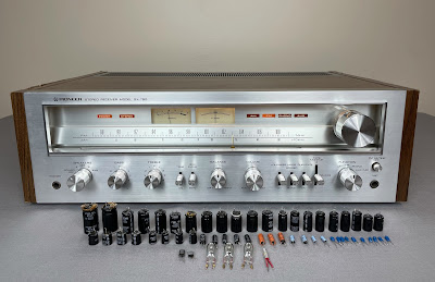
Today I'm showcasing a Pioneer SX-750 stereo receiver that came in for restoration. The SX-750 was and still is one of the most popular and well-respected receivers from the 70's. It was initially introduced in 1976 and made through 1978. The receiver produces 50 watts per channel into 8 ohms with no more than 0.1% total harmonic distortion. The unit is quite heavy and weighs about 30 pounds without a package. As Pioneer states in its 1976's brochure "for a practically-priced integrated receiver, Pioneer's SX-750 delivers an astonishing amount of state-of-the-art perfection. It is innovative, attractive, and value-packed". And it's hard to argue! According to the Pioneer database, this particular unit was manufactured in March 1978.
The restoration of the smaller brothers of SX-750 can be found on my blog here: Pioneer SX-450 receiver restoration and Pioneer SX-650 receiver restoration.
This particular receiver came in for a restoration with a broken original Speaker Selector/Power switch. The owner took it up to a local repair shop to fix this issue but the technician just simply bypassed the original switch with a new one. The new switch was assembled on the left side panel. This is definitely not the best solution to the problem but this switch is a common issue on those Pioneer receivers. The switch can't be fixed by cleaning and there are no more new replacements available on the market. The best solution would be to disassemble the switch, clean up carbonized contacts with very fine sandpaper and then assemble it. I have tried to repair such a switch several times in the past but the reliability of the repaired switch is always in question. I usually prefer to replace it with a new switch if it is available. So, the owner decided to leave it alone and replace it probably later.
Bypassed Speaker Selector/Power switch - installed in the repair shop
Power Supply & Protection Assembly (AWR-099)
The power supply & protection circuits are assembled on one board (AWR-099). This board has 17 aluminum electrolytic capacitors: C1 thru C13, and C15 thru C18.
The original coupling capacitors C1 & C2 installed on this board are failure-prone sky blue Sanyo e-caps. As expected, the measured capacitance of these two e-caps is outside of factory capacitance tolerance. For more information about sky blue Sanyo e-caps refer to my previous post on Pioneer SX-828 restoration. I replaced them with high-quality film polyester Kemet capacitors.
The original aluminum e-caps C17 and C18 are rated at 330uF/50V. However, these two capacitors are running very close to their maximum rated voltage in the circuit. As a result, they are aging very fast and can completely fail at any time. I replaced them with 330uF/63V low impedance and high-reliability Nichicon UPM caps. It will substantially improve the reliability and extend a capacitor lifespan.
As can be seen from the test results below, at least five more original e-caps from this board are also outside of factory capacitance tolerance. I replaced all remaining aluminum e-caps with low impedance Nichicon UPW/UPM caps.
Test results on original capacitors removed from the power supply & protection board:
C1: rated capacitance – 0.22uF, measured – 0.29uF, ESR – N/A, deviation: +32%
C2: rated capacitance – 0.22uF, measured – 0.32uF, ESR – N/A, deviation: +46%
C3: rated capacitance – 330uF, measured – 362uF, ESR – 0.12Ω, deviation: +10%
C4: rated capacitance – 330uF, measured – 374uF, ESR – 0.11Ω, deviation: +13%
C5: rated capacitance – 3.3uF, measured – 4.2uF, ESR – 0.8Ω, deviation: +27%
C6: rated capacitance – 220uF, measured – 218uF, ESR – 0.08Ω, deviation: -1%
C7: rated capacitance – 220uF, measured – 151uF, ESR – 0.12Ω, deviation: -31%
C8: rated capacitance – 100uF, measured – 73uF, ESR – 0.12Ω, deviation: -27%
C9: rated capacitance – 100uF, measured – 95uF, ESR – 0.13Ω, deviation: -5%
C10: rated capacitance – 100uF, measured – 95uF, ESR – 0.14Ω, deviation: -5%
C11: rated capacitance – 4.7uF, measured – 6.1uF, ESR – 1.48Ω, deviation: +30%
C12: rated capacitance – 220uF, measured – 138uF, ESR – 0.14Ω, deviation: -37%
C13: rated capacitance – 100uF, measured – 95uF, ESR – 0.04Ω, deviation: -5%
C15: rated capacitance – 100uF, measured – 84uF, ESR – 0.16Ω, deviation: -16%
C16: rated capacitance – 100uF, measured – 90uF, ESR – 0.06Ω, deviation: -10%
C17: rated capacitance – 330uF, measured – 261uF, ESR – 0.01Ω, deviation: -21%
C18: rated capacitance – 330uF, measured – 185uF, ESR – 0.01Ω, deviation: -44%
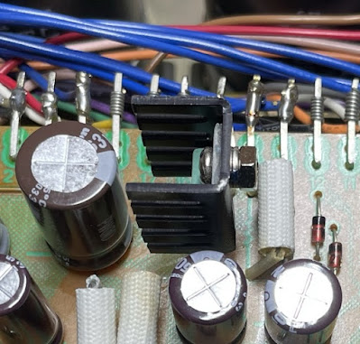
The original PNP transistor 2SB507 installed on this board is running pretty hot under normal operating conditions (by circuit design) but has no heat sink. I mounted a low-profile heat sink on this transistor to improve heat dissipation. The heat sink is small enough and doesn't touch any nearby components. The manufacturer's part number is 577404B00000G (Aavit).
Low profile heat sink mounted on original PNP transistor Q12
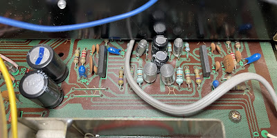
Power supply & protection assembly (AWR-099) - before and after
Filter & Muting Assembly (AWM-094)
The filter and muting circuits are assembled on one board (AWM-094). The access to the foil side of this board is blocked by a bunch of wires. I recommend removing the metal angle supporting this board to get better access. Otherwise, there is a high risk of touching some of these wires with a hot soldering iron. Don't forget to screw back a small ground plate with a wire coming from the power supply & protection board (pin #12) after the servicing is done. Also, re-flow the pad under the screw to improve ground contact.
This board has three solid tantalum capacitors C1, C2, C7, and two aluminum electrolytic capacitors C3 and C5. The capacitors C1 and C2 installed in the signal path after the low pass filter were replaced with modern low leakage Nichicon UKL capacitors. The capacitor C7 was replaced with a high-quality film polyester WIMA MKS2 cap. And the remaining two capacitors C3 and C5 were replaced with low impedance Nichicon UPW/UPM caps.
Test results on original capacitors removed from the filter and muting board:
C1: rated capacitance – 2.2uF, measured – 2.1uF, ESR – 4.1Ω, deviation: -5%
C2: rated capacitance – 2.2uF, measured – 2.2uF, ESR – 3.2Ω, deviation: 0%
C3: rated capacitance – 10uF, measured – 12uF, ESR – 0.56Ω, deviation: +20%
C5: rated capacitance – 100uF, measured – 87uF, ESR – 0.06Ω, deviation: -13%
C7: rated capacitance – 1uF, measured – 1uF, ESR – 1.12Ω, deviation: 0%
Filter & muting assembly (AWM-094) - before and after
Tuner, AF, & Control Assembly (AWE-073)
The tuner, phono equalizer, and microphone circuits are all assembled on the same board (AWE-073).
The phono equalizer circuit has four solid tantalum e-caps installed in the input (C82, C83) and output (C98, C99) signal path, two filtering aluminum e-caps (C84, C85), and two DC blocking aluminum e-caps (C88, C89) in the RIAA feedback loop. All original tantalum capacitors were replaced with low leakage Nichicon UKL caps. The remaining four aluminum e-caps were replaced with low impedance Nichicon UPW caps.
Test results on original capacitors removed from the phono equalizer circuit:
C82: rated capacitance – 2.2uF, measured – 2.3uF, ESR – 1.48Ω, deviation: +5%
C83: rated capacitance – 2.2uF, measured – 2.2uF, ESR – 1.85Ω, deviation: 0%
C84: rated capacitance – 220uF, measured – 278uF, ESR – 0.02Ω, deviation: +26%
C85: rated capacitance – 220uF, measured – 280uF, ESR – 0.02Ω, deviation: +27%
C88: rated capacitance – 100uF, measured – 112uF, ESR – 0.31Ω, deviation: +12%
C89: rated capacitance – 100uF, measured – 112uF, ESR – 0.32Ω, deviation: +12%
C98: rated capacitance – 2.2uF, measured – 2.2uF, ESR – 2.71Ω, deviation: 0%
C99: rated capacitance – 2.2uF, measured – 2.1uF, ESR – 2.22Ω, deviation: -5%
Phono equalizer circuit - before and after
The microphone circuit in the Pioneer SX-750 is a two-stage transistor amplifier. The original PNP transistor installed in the 1st stage is a notorious 2SA725 transistor. This transistor becomes very noisy over time and I replaced it with a modern low noise Fairchild KSA992 transistor. The original NPN transistor installed in the 2nd stage is a 2SC1344 transistor. This transistor is also prone to failure. I replaced it with a modern low noise Fairchild KSC1845 transistor.
According to the service manual, the input (C102) and output (C105) coupling capacitors in the microphone circuit are supposed to be solid tantalum e-caps. However, in this particular unit, the tantalum e-cap was installed only in the output position. In the input position, a solid low leakage aluminum e-cap was installed. I replaced both coupling capacitors with modern low leakage Nichicon UKL caps.
The aluminum e-cap C106 was originally rated at 220uF/35V. I replaced it with a 220uF/50V low impedance Nichicon UPW cap. The maximum voltage rating was increased since this capacitor is running very close to its maximum rated voltage in the circuit.
Test results on original capacitors removed from the microphone circuit:
C102: rated capacitance – 2.2uF, measured – 2.6uF, ESR – 4.01Ω, deviation: +18%
C105: rated capacitance – 2.2uF, measured – 2.5uF, ESR – 3.86Ω, deviation: +14%
C106: rated capacitance – 220uF, measured – 200uF, ESR – 0.02Ω, deviation: -9%
Microphone circuit -before and after (sorry, it's very hard to take a good picture of this circuit, two transistors (Q11, Q12) are located behind the rotary switch)
Tone Control Assembly (AWG-046)
The tone control board has two coupling Sanyo e-caps (C1, C2) installed in the input signal path, two low leakage aluminum e-caps (C9, C10) installed in the output signal path, two aluminum e-caps (C3, C4) in the feedback loop, and two filtering aluminum e-caps (C7, C8). The original coupling capacitors C1 and C2 are failure-prone sky blue Sanyo capacitors and I replaced them with high-quality film polyester WIMA MKS2 caps. Two original low leakage capacitors (C9, C10) were replaced with modern low leakage Nichicon UKL caps. And the remaining four aluminum e-caps were replaced with low impedance Nichicon UPW caps.
Test results on original capacitors removed from the tone control board:
C1: rated capacitance – 0.47uF, measured – 0.73uF, ESR – N/A, deviation: +55%
C2: rated capacitance – 0.47uF, measured – 0.56uF, ESR – N/A, deviation: +19%
C3: rated capacitance – 100uF, measured – 107uF, ESR – 0.31Ω, deviation: +7%
C4: rated capacitance – 100uF, measured – 112uF, ESR – 0.24Ω, deviation: +12%
C7: rated capacitance – 220uF, measured – 244uF, ESR – 0.01Ω, deviation: +11%
C8: rated capacitance – 220uF, measured – 242uF, ESR – 0.02Ω, deviation: +10%
C9: rated capacitance – 4.7uF, measured – 6.5uF, ESR – 4.2Ω, deviation: +38%
C10: rated capacitance – 4.7uF, measured – 6.5uF, ESR – 3.6Ω, deviation: +38%
Tone control assembly (AWG-046) - before and after
Power Amplifier Assembly (AWH-046)
The power amplifier board has two solid tantalum capacitors (C1, C2), and six aluminum e-caps (C7 thru C10, C13, C14). The tantalum capacitors C1 and C2 installed in the signal path were replaced with film polyester WIMA MKS2 caps. The e-caps C7 and C8 installed in the negative feedback loop were replaced with low impedance Nichicon UPW caps. The original decoupling e-caps C9 and C10 are rated at 100uF/35V and I replaced them with 100uf/50V low impedance Nichicon UPW caps. The remaining emitter bypass e-caps C13 and C14 were also replaced with low impedance Nichicon UPW caps.
Test results on original capacitors removed from the power amplifier board:
C1: rated capacitance – 1uF, measured – 1uF, ESR – 2.8Ω, deviation: 0%
C2: rated capacitance – 1uF, measured – 1uF, ESR – 4.2Ω, deviation: 0%
C7: rated capacitance – 220uF, measured – 263uF, ESR – 0.14Ω, deviation: +20%
C8: rated capacitance – 220uF, measured – 264uF, ESR – 0.12Ω, deviation: +20%
C9: rated capacitance – 100uF, measured – 90uF, ESR – 0.11Ω, deviation: -10%
C10: rated capacitance – 100uF, measured – 95uF, ESR – 0.12Ω, deviation: -5%
C13: rated capacitance – 220uF, measured – 271uF, ESR – 0.14Ω, deviation: +23%
C14: rated capacitance – 220uF, measured – 252uF, ESR – 0.12Ω, deviation: +15%
Power amplifier board - before and after
Dial and Stereo Indicator Lamps
Three original dial illumination lamps were replaced with new 8V/300A incandescent lamps. The original stereo indicator lamp in this unit was burned out and I replaced it with a new 8V/60mA lamp.
Idle Current Adjustment
The idle current adjustment is clearly described in the service manual. DC voltmeter should be connected between pins 1 and 6 (left channel), or between pins 11 and 16 (right channel). The bias measured across two emitter resistors R31 & R33 (left channel) or R32 & R34 (right channel) should be adjusted to ~30mV with trimmers VR1 or VR2, respectively. Since each emitter resistor is rated at 0.5Ω, the idle current can be calculated to be 30mV/(0.5Ω + 0.5Ω) = 30mA.
Bias on the left and right channel after restoration
Output Power Test
At the end of my restoration, I loaded this receiver with a low inductance 8Ω/100W dummy resistor for each channel, connected my oscilloscope across the speaker terminals, and applied a sine-wave signal of 1kHz to the AUX jacks. The output sine-wave signal was perfectly symmetrical on both channels with no clipping up to 21.23 VRMS (left channel) and 21.22 VRMS (right channel). It corresponds to the output power of 56.3W on the left channel and 56.3W on the right channel.
Output power test
As usual, all the knobs and the front panel were gently cleaned in warm water with dish soap. All knobs were also slightly polished by Mothers Mag & Aluminum polish to remove some small spots of aluminum oxidation. All the pots and switches were also thoroughly cleaned with DeoxIT 5% contact cleaner and lubricated with DeoxIT FaderLube 5% spray.
The final result can be seen in the photos below. The sound is crystal clear, smooth, and well detailed. Please watch a short demo video at the end of this post. Thank you for reading.
Pioneer SX-750 - after restoration
Demo video after repair & restoration


Thanks for posting, very nice job , congratulations
ReplyDeleteNice Job Oleg! I'm glad to see nice restorations like this preserving these wonderful examples of stereo in that all too short magical time period for Hi Fi. When they were new I was a teenager and only dreamed of owning a serious one. Now I have 13 Pioneers that I am about to restore and that includes three SX-750s.
ReplyDelete