Home

Friday, December 16, 2022

Marantz 1040 Stereo Integrated Amplifier Restoration

Unit: Stereo Integrated Amplifier
Manufacturer: Marantz
Model: 1040
SN: 1634

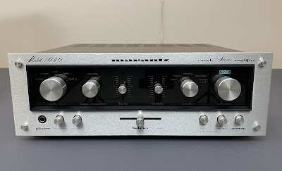
Today I'm showcasing a Marantz 1040 stereo integrated amplifier that came in for restoration. This model was manufactured from 1974 to 1978. It produces 20 watts per channel into 8 ohms with no more than 0.3% total harmonic distortion. The optional walnut veneer cabinet for this model is WC-10. The retail price in 1975 was $199.95 (Ref. Marantz Dealer Price List).

Marantz 1040 is a service-friendly amplifier because of very good access to each PCB.

Marantz_1040_After restoration

Power Supply Board (P800)

The power supply unit provides +35V DC (pin J807) to the phono amplifier and tone amplifier boards.
 
Four electrolytic capacitors (C803, C804, C805, and C806) installed on this board were replaced with low impedance and high-reliability Nichicon UPM e-caps. The dried glue under each capacitor was carefully removed. The original e-caps were tested with an Atlas ESR70 capacitance meter and the results are below.

Test results on original capacitors removed from the power supply board:

C803: rated capacitance – 330uF, measured – 335uF, ESR – 0.01Ω, deviation: +2%
C804: rated capacitance – 220uF, measured – 251uF, ESR – 0.02Ω, deviation: +14%
C805: rated capacitance – 100uF, measured – 122uF, ESR – 0.05Ω, deviation: +22%
C806: rated capacitance – 220uF, measured – 272uF, ESR – 0.01Ω, deviation: +24%

Power supply board - before and after

Marantz_1040_Power Supply Board (P800)_before servicing

Marantz_1040_Power Supply Board (P800)_after servicing

Tone Amplifier Board (PE01)

The tone amplifier board has six low leakage capacitors (CE03, CE04, CE07, CE08, CE09, CE10) installed in the signal path, two bi-polar e-caps (CE11, CE12), and three aluminum electrolytic capacitors (CE05, CE06, CE13). The original low leakage e-caps with a rated capacitance of 4.7uF were replaced with modern low leakage Nichicon UKL caps. The other two low leakage e-caps (CE07 and CE08) were replaced with high-quality film polyester WIMA caps. The original bi-polar caps (CE11 and CE12) were replaced with modern bi-polar Nichicon UES caps. And, the remaining aluminum e-caps were replaced with low impedance Nichicon UPW/UPM caps.

Test results on original capacitors removed from the tone amplifier board:

CE03: rated capacitance – 4.7uF, measured – 4.7uF, ESR – 1.39Ω, deviation: +0%
CE04: rated capacitance – 4.7uF, measured – 4.9uF, ESR – 1.26Ω, deviation: +4%
CE05: rated capacitance – 10uF, measured – 11uF, ESR – 0.57Ω, deviation: +10%
CE06: rated capacitance – 10uF, measured – 11uF, ESR – 0.61Ω, deviation: +10%
CE07: rated capacitance – 1uF, measured – 0.8uF, ESR – 3.4Ω, deviation: -20%
CE08: rated capacitance – 1uF, measured – 0.8uF, ESR – 3.6Ω, deviation: -20%
CE09: rated capacitance – 4.7uF, measured – 4.7uF, ESR – 1.31Ω, deviation: +0%
CE10: rated capacitance – 4.7uF, measured – 4.7uF, ESR – 1.54Ω, deviation: +0%
CE11: rated capacitance – 4.7uF, measured – 4.6uF, ESR – 1.39Ω, deviation: -2%
CE12: rated capacitance – 4.7uF, measured – 4.5uF, ESR – 1.4Ω, deviation: -4%
CE13: rated capacitance – 100uF, measured – 114uF, ESR – 0.05Ω, deviation: +14%

Tone amplifier board - before and after

Marantz_1040_Tone Amplifier Board (PE01)_before servicing

Marantz_1040_Tone Amplifier Board (PE01)_after servicing

Phono Amplifier Board (P400)

The phono amplifier board has four low leakage capacitors (C401, C402, C413, C414) installed in the signal path, and four aluminum electrolytic capacitors (C409, C410, C415, C416). The original low leakage e-caps (C401 and C402) with a rated capacitance of 4.7uF were replaced with modern low leakage Nichicon UKL caps. The other two low leakage e-caps (C413 and C414) were replaced with film polyester WIMA caps. The remaining aluminum e-caps were replaced with low impedance Nichicon UPW caps. Note that the capacitance deviation of the two original e-caps (C409 and C410) is almost 70% of the nominal value.

Test results on original capacitors removed from the phono amplifier board:

C401: rated capacitance – 4.7uF, measured – 4.5uF, ESR – 2.1Ω, deviation: -4%
C402: rated capacitance – 4.7uF, measured – 4.6uF, ESR – 1.5Ω, deviation: -2%
C409: rated capacitance – 100uF, measured – 167uF, ESR – 0.19Ω, deviation: +67%
C410: rated capacitance – 100uF, measured – 168uF, ESR –0.14 Ω, deviation: +68%
C413: rated capacitance – 1uF, measured – 0.8uF, ESR – 2.8Ω, deviation: -20%
C414: rated capacitance – 1uF, measured – 0.8uF, ESR – 2.6Ω, deviation: -20%
C415: rated capacitance – 100uF, measured – 118uF, ESR – 0.23Ω, deviation: +18%
C416: rated capacitance – 47uF, measured – 53uF, ESR – 0.26Ω, deviation: +13%

Phone amplifier board - before and after

Marantz_1040_Phono Amplifier Board (P400)_before servicing

Marantz_1040_Phono Amplifier Board (P400)_after servicing

Main Amplifier Board (P700)

The main amplifier board in Marantz 1040 is the most difficult board for servicing. This model does not have transistor sockets for power transistors. The leads of the four power transistors are directly soldered to wires. This design makes it difficult to disconnect the board from the heat sink since all transistors have to be de-soldered from the wires. This board can still be serviced with all wires connected, but in this case, the power transistors cannot be tested for current gain.

The main amplifier board has four low leakage e-caps (C701, C702, C705, C706) and five aluminum electrolytic capacitors (C709, C710, C711, C712, and C717). The original low leakage e-caps were replaced with modern low leakage Nichicon UKL caps. The remaining aluminum e-caps were replaced with low impedance Nichicon UPW caps. Note that the original e-cap C705 has only ~50% of the rated capacity.

Test results on original capacitors removed from the main amplifier board:

C701: rated capacitance – 3.3uF, measured – 3.1uF, ESR – 3.4Ω, deviation: -6%
C702: rated capacitance – 3.3uF, measured – 2.9uF, ESR – 3.9Ω, deviation: -12%
C705: rated capacitance – 47uF, measured – 25uF, ESR – 1.18Ω, deviation: -47%
C706: rated capacitance – 47uF, measured – 44uF, ESR – 0.14Ω, deviation: -6%
C709: rated capacitance – 100uF, measured – 121uF, ESR – 0.18Ω, deviation: +21%
C710: rated capacitance – 100uF, measured – 119uF, ESR – 0.34Ω, deviation: +19%
C711: rated capacitance – 47uF, measured – 52uF, ESR – 0.16Ω, deviation: +11%
C712: rated capacitance – 47uF, measured – 51uF, ESR – 0.64Ω, deviation: +9%
C717: rated capacitance – 10uF, measured – 11uF, ESR – 2.6Ω, deviation: +10%

The first stage of the main amplifier circuit is a differential pair amplifier consisting of two amplifying transistors with a common emitter: H701/H703 (left channel) and H702/H704 (right channel). The original PNP transistors installed in these positions are 2SA722. These transistors are not on my list of notorious transistors prone to failure. However, the owner of this amplifier complained about some distortion from the right channel and I decided to test the original 2SA722s to make sure they are well matched by current gain. So, I di-soldered all four transistors and tested them with Atlas DCA55 semiconductor analyzer. The pair of transistors from the left channel was very well matched (the current gain of H701 and H703 is 234 and 235, respectively). But the pair of original 2SA722s from the right channel had a mismatch of ~29% (the current gain of H702 and H704 is 273 and 353, respectively). Transistors installed in the differential pair amplifier are supposed to be gain matched as much as possible and a 29% mismatch is a lot for proper operation. So, I replaced the original 2SA722 transistors in both channels with new Fairchild KSA992 transistors. Before installation, each pair of KSA992 transistors was carefully matched by current gain and base-emitter voltage. 

Test results on original 2SA722 transistors

H701 (left channel): hfe - 234, Vbe - 0.750V 
H703 (left channel): hfe - 235, Vbe - 0.752V

H702 (right channel): hfe - 273, Vbe - 0.788V 
H704 (right channel): hfe - 353, Vbe - 0.789V

Test results on new KSA992 transistors

H701 (left channel): hfe - 403, Vbe - 0.760V 
H703 (left channel): hfe - 403, Vbe - 0.759V

H702 (right channel): hfe - 405, Vbe - 0.759V 
H704 (right channel): hfe - 406, Vbe - 0.761V

Main amplifier board - before and after

Marantz_1040_Main Amplifier Board (P700)_before servicing

Marantz_1040_Main Amplifier Board (P700)_after servicing

Power Transistors

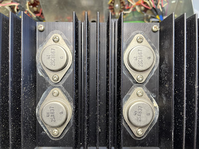
The original power transistors were removed, cleaned, and tested with an Atlas DCA55 semiconductor analyzer. The test showed that the left channel NPN transistor (H002, 2SC1667) has a shunt between the base and the emitter. I measured the resistance between the base and emitter and it was very low at ~8.3kΩ. The remaining three transistors passed the test. 

NPN power transistor 2SC1667 from the left channel - shunt between the base and emitter

Marantz_1040_H002_resistor shunt

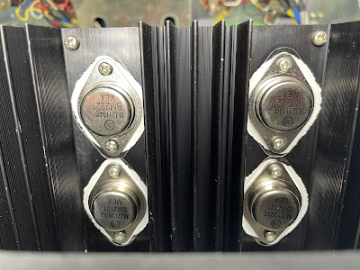
I don't have any new 2SC1667 transistors in stock and decided to replace all original power transistors with new ON Semiconductor transistors. Keep in mind that the NPN transistor 2SC1667 is a complement to the PNP transistor 2SA837. So, you can not install another NPN power transistor with similar parameters instead of 2SC1667. Well, you can but it is not the right thing to do. I replaced the original 2SC1667/2SA837 transistors in each channel with new MJ21194G/MJ21193G transistors. The new transistors are specifically designed for high-power audio output, have excellent gain linearity, and complement each other. The new Mica pads and fresh thermal compound were applied between each power transistor and heat sink. The fresh thermal compound was also applied to the thermal tracking diodes H005 and H006.

Original and new ON Semiconductor power transistors

Marantz_1040_Power Transistors_original

Marantz_1040_Power Transistors_new

Pilot Lamp

The old pilot lamp was replaced with a new incandescent lamp. The yellowish old vellum paper in front of the pilot lamp was replaced as well.

Old and new pilot lamp

Marantz_1040_Pilot Lamp_old

Marantz_1040_Pilot Lamp_new

DC offset and Bias Adjustments

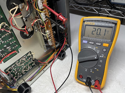
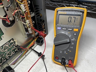
The Bias is measured across two emitter resistors. The voltage drop across resistors R751 and R753 should be adjusted to ~20mV DC with the trimming resistor R763 (the DC voltmeter is connected between pins J709 and J711). This is a bias on the left channel. And on the right channel, the voltage drop across resistors R752 and R754 should be adjusted to ~20mV DC with the trimming resistor R764 (the DC voltmeter is connected between pins J720 and J721).

The DC offset is measured between pin J707 and ground on the left channel, and between pin J718 and ground on the right channel. It should be adjusted as close to zero volts as possible with the trimming resistors R761 and R762, respectively.

Bias on the left and right channels after restoration

Marantz_1040_Bias_left channel

Marantz_1040_Bias_right channel

DC offset on the left and right channels after restoration

Marantz_1040_DC Offset_left channel

Marantz_1040_DC Offset_right channel

Output Power Test

The final output power test was performed at the end of my restoration. The amplifier was loaded with a low inductance 8Ω/100W dummy resistor for each channel. The oscilloscope was connected across the speaker terminals and a sine-wave signal of 1kHz was applied to the AUX jacks. The output sine-wave signal was perfectly symmetrical on both channels with no clipping up to 13.48 VRMS (left channel) and 13.41 VRMS (right channel). It corresponds to the output power of 22.7W on the left channel and 22.5W on the right channel.

Output power test

Marantz_1040_Output Power Test

As usual, all the knobs and the face plate were gently cleaned in warm water with dish soap. All controls have been cleaned with DeoxIT 5% contact cleaner and lubricated with DeoxIT FaderLube 5% spray.

The final result can be seen in the photos below. The amplifier looks like new again. The sound is excellent, with deep bass and clear highs. Please watch a short demo video at the end of this post. Thank you for reading.

Marantz 1040 - after restoration

Marantz_1040_After restoration

Marantz_1040_After restoration_with parts

Demo video after repair & restoration

Saturday, December 3, 2022

Sherwood S-7210 Receiver Restoration

Unit: AM/FM Stereo Receiver
Manufacturer: Sherwood
Model: S-7210
SN: 511645

Today I'm showcasing a Sherwood S-7210 AM/FM stereo receiver that came in for restoration. This model was introduced in 1974 and produces 26 watts per channel into 8 ohms with less than 0.6% total harmonic distortion. The damping factor is 30. The list price in 1974 was $299.95 (Ref. High Fidelity Magazine, September 1974, page 27).

The Sherwood S-7210 is a service-friendly receiver. Each board can be easily accessed for servicing.

Sherwood_S-7210_After Restoration

Selector & Pre-Amp Board

The selector & pre-amp board has two solid tantalum capacitors (C501a, C501b) and twelve aluminum electrolytic capacitors (C503a, C503b, C504a, C504b, C505a, C505b, C506a, C506b, C512, C513, C514, C515). The solid tantalum capacitors are installed in the input signal path and I replaced them with modern low leakage Nichicon UKL e-caps. The ordinary aluminum e-caps C505a and C505b installed in the output signal path were replaced with high-quality film polyester WIMA caps. And, the remaining aluminum capacitors were replaced with low impedance Nichicon UPW caps.

The original e-caps were tested with an Atlas ESR70 capacitance meter and the results are below. Five of the fourteen capacitors are outside of factory spec.

Test results on original capacitors removed from the selector & pre-amp board:

C501a: rated capacitance – 4.7uF, measured – 5.3uF, ESR – 1.58Ω, deviation: +13%
C501b: rated capacitance – 4.7uF, measured – 4.9uF, ESR – 1.92Ω, deviation: +4%
C503a: rated capacitance – 22uF, measured – 28uF, ESR – 1.12Ω, deviation: +27%
C503b: rated capacitance – 22uF, measured – 28uF, ESR – 1.04Ω, deviation: +27%
C504a: rated capacitance – 33uF, measured – 36uF, ESR – 0.55Ω, deviation: +9%
C504b: rated capacitance – 33uF, measured – 34uF, ESR – 0.66Ω, deviation: +3%
C505a: rated capacitance – 1uF, measured – 1.3uF, ESR – 2.9Ω, deviation: +30%
C505b: rated capacitance – 1uF, measured – 1.2uF, ESR – 2.9Ω, deviation: +20%
C506a: rated capacitance – 10uF, measured – 11uF, ESR – 1.35Ω, deviation: +10%
C506b: rated capacitance – 10uF, measured – 11uF, ESR – 1.42Ω, deviation: +10%
C512: rated capacitance – 33uF, measured – 41uF, ESR – 0.72Ω, deviation: +24%
C513: rated capacitance – 33uF, measured – 41uF, ESR – 0.81Ω, deviation: +24%
C514: rated capacitance – 10uF, measured – 11uF, ESR – 1.39Ω, deviation: +10%
C515: rated capacitance – 10uF, measured – 11uF, ESR – 1.42Ω, deviation: +10%

Two NPN transistors (TR502a & TR502b) installed on this board are Toshiba 2SC1000. This transistor is known to get noisy over time. I replaced the original 2SC1000 transistors with modern low-noise Fairchild KSC1845s. The new transistor has the same pinout as the original one.

Selector & pre-amp board - before and after

Sherwood_S-7210_Selector & Pre Amp Board_before servicing

Sherwood_S-7210_Selector & Pre Amp Board_after servicing

Main Amp & Power Supply Board

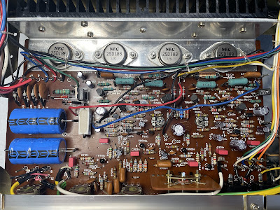
The power supply, tone control amplifier, and main amplifier are all located on a single PCB.

The power supply circuit provides -11.3V DC to the tuner board, and balanced power to the main power amplifier from the bridge rectifier and two filter capacitors. The circuit has two aluminum electrolytic capacitors (C807, C808) and two axial filter capacitors (C805, C806). The two aluminum e-caps were replaced with low impedance and high-reliability Nichicon UPW caps. Both axial 4700uF/35V filter capacitors were replaced with new 4700uF/40V Vishay 021ASM series caps. I usually don't replace large filter capacitors in vintage gears unless their ESR is high or the measured capacitance exceeds the nominal one by more than +/- 10%. But it makes sense in this particular case since the ESR of each original filter cap is relatively high and the measured capacitance is very low in comparison to the nominal value.

Test results on original capacitors removed from the power supply circuit:

C805: rated capacitance – 4700uF, measured – 2362uF, ESR – 0.13Ω, deviation: -50%
C806: rated capacitance – 4700uF, measured – 2214uF, ESR – 0.14Ω, deviation: -53%
C807: rated capacitance – 33uF, measured – 32uF, ESR – 3.8Ω, deviation: -3%
C808: rated capacitance – 33uF, measured – 33uF, ESR – 3.8Ω, deviation: 0%

The tone control circuit has six aluminum electrolytic capacitors (C901a, C901b, C902a, C902b, C906a, C906b) installed in the signal path, and two filtering aluminum e-caps (C908 and C909). Four ordinary aluminum e-caps with a nominal capacitance of 1uF were replaced with film polyester WIMA caps to improve the signal-to-noise ratio. The other two e-caps with a nominal capacitance of 4.7uF were replaced with modern low leakage Nichicon UKL caps. And the remaining filtering aluminum capacitors were replaced with low impedance Nichicon UPM caps.

Note, that one of the original capacitors installed in this circuit completely failed the test (C906b, open circuit).

Test results on original capacitors removed from the tone control circuit:

C901a: rated capacitance – 1uF, measured – 1.3uF, ESR – 1.66Ω, deviation: +30%
C901b: rated capacitance – 1uF, measured – 1.2uF, ESR – 2.4Ω, deviation: +20%
C902a: rated capacitance – 1uF, measured – 1.2uF, ESR – 2.2Ω, deviation: +20%
C902b: rated capacitance – 1uF, measured – 1.2uF, ESR – 2.1Ω, deviation: +20%
C906a: rated capacitance – 4.7uF, measured – 5.1uF, ESR – 1.8Ω, deviation: +9%
C906b: rated capacitance – 4.7uF, measured – open circuit
C908: rated capacitance – 220uF, measured – 298uF, ESR – 0.14Ω, deviation: +36%
C909: rated capacitance – 470uF, measured – 508uF, ESR – 0.08Ω, deviation: +8%

The main amplifier circuit has nine aluminum electrolytic capacitors: C601a, C601b, C604a, C604b, C605a, C605b, C606a, C606b, and C611. Two of them (C601a and C601b) are installed in the input signal path. I replaced them with film polyester WIMA caps to improve the signal-to-noise ratio. The other e-caps were replaced with low impedance Nichicon UPW/UHE caps.

Note, that two out of nine original capacitors installed in this circuit completely failed the test (C605b and C611, open circuit). Also, the measured capacitance of e-cap C604a is very close to the nominal but its ESR is very high.

Test results on original capacitors removed from the main amplifier circuit:

C601a: rated capacitance – 1uF, measured – 1.2uF, ESR – 1.74Ω, deviation: %
C601b: rated capacitance – 1uF, measured – 1.2uF, ESR – 2.4Ω, deviation: %
C604a: rated capacitance – 33uF, measured – 34uF, ESR – 8.3Ω, deviation: %
C604b: rated capacitance – 33uF, measured – 33uF, ESR – 3.5Ω, deviation: %
C605a: rated capacitance – 33uF, measured – 33uF, ESR – 2.8Ω, deviation: %
C605b: rated capacitance – 33uF, measured – open circuit
C606a: rated capacitance – 100uF, measured – 87uF, ESR – 0.19Ω, deviation: %
C606b: rated capacitance – 100uF, measured – 86uF, ESR – 0.22Ω, deviation: %
C611: rated capacitance – 4.7uF, measured – open circuit

The first stage of the main amplifier circuit is a differential pair amplifier consisting of two amplifying transistors with a common emitter: TR601a/TR602a (left channel) and TR601b/TR602b (right channel). The original PNP transistors installed in these positions are 2SA640. These transistors are not on my list of notorious transistors prone to failure. However, before I started servicing this receiver I measured the DC offset across the speaker terminals and noticed a relatively high (but still safe) voltage in the right channel. The measured DC offset in the left channel was ~14mV (perfectly good) but in the right channel, the measured voltage was ~55mV. This voltage should be as close to zero volts as possible within +/- 50mV. Usually, if this voltage is relatively high (but still within a safe range) the problem might be with mismatched transistors installed in the differential amplifier. So, I unsoldered the original 2SA640 transistors and tested each pair with Atlas DCA55 semiconductor analyzer. The measured current gain of two transistors TR601a and TR602a (left channel) was 542 and 491, respectively. It gives an ~10% difference between them. Not too bad, but remember that transistors installed in the differential amplifier are supposed to be closely matched to operate properly in the circuit. Then, I measured the current gain of two transistors TR601b and TR602b installed in the right channel. The measured gain was 563 and 449, respectively. It gives ~25% difference between them which is rather substantial. 

I replaced all original 2SA640's with modern Fairchild KSA992 transistors. Before installation, each pair of KSA992 transistors was carefully matched by current gain and base-emitter voltage. After the new transistors were installed the DC offset on each channel became close to 0V within +/- 10mV.

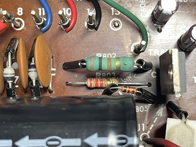
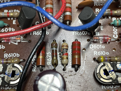
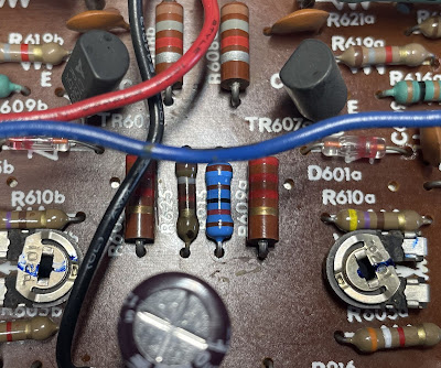
I also noticed that the body of two resistors (R803 and R915) is damaged. The R803 is installed in the power supply circuit, and the R915 is in the tone control circuit. I didn't see any signs of overheating though. So, I am not sure what caused their damage. Despite the body being damaged the measured resistance of R803 and R915 is still very close to the nominal resistance. It makes sense to replace these two resistors as a part of preventive maintenance. The original R803 was replaced with a new Vishay power metal film resistor. And the R915 was replaced with a new KOA Speer metal film resistor.

The body of two original resistors R803 and R915 is damaged

Sherwood_S-7210_R803_damaged body

Sherwood_S-7210_R915_damaged body

New resistors R803 and R915 are installed

Sherwood_S-7210_R803_new resistor

Sherwood_S-7210_R915_new resistor

Main amp & power supply board - before and after

Sherwood_S-7210_Main Amp & Power Supply Board_before servicing

Sherwood_S-7210_Main Amp & Power Supply Board_after servicing

Dial and Meter Lamps

The dial and meter lamps in this unit have been already replaced with warm white LED lamps by the owner.

New dial and meter lamps - warm white LEDs

Sherwood_S-7210_Dial Lamps_warm white LED lamps

Sherwood_S-7210_Meter Lamp_warm white LED lamp

Output Power Test

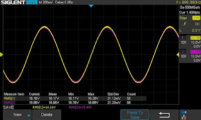
The final output power test was performed at the end of my restoration. The receiver was loaded with a low inductance 8Ω/100W dummy resistor for each channel. The oscilloscope was connected across the speaker terminals and a sine-wave signal of 1kHz was applied to the AUX jacks. The output sine-wave signal was perfectly symmetrical on both channels with no clipping up to 16.16 VRMS (left channel) and 15.88 VRMS (right channel). It corresponds to the output power of 32.6W on the left channel and 31.5W on the right channel.

Output power test

Sherwood_S-7210_Output Power Test

As usual, all the knobs and the front panel were gently cleaned in warm water with dish soap. All controls have been cleaned with DeoxIT 5% contact cleaner and lubricated with DeoxIT FaderLube 5% spray.

The final result can be seen in the photos below. Please watch a short demo video at the end of this post. Thank you for reading.

Sherwood S-7210 - after restoration

Sherwood_S-7210_After Restoration

Sherwood_S-7210_After Restoration_with parts

Demo video after repair & restoration