Unit: AM/FM Stereo Receiver
Manufacturer: Sansui
Manufacturer: Sansui
Model: 661
SN: 023123523
I bought this receiver a few months ago from the original owner along with a Sansui QS-500 quadraphonic rear channel amplifier and Sansui RA-500 reverberation amplifier. All three units have never been serviced before but are still in great cosmetic condition. It is certainly worth restoring.
The Sansui 661 is a great mid-range receiver. It is third from the top-of-the-line receivers in the Sansui lineup at the time: 881, 771, 661, 551, 441, 331, 221. It has an attractive champaigne-gold front panel and an all-wood cabinet. It was manufactured from 1970 to 1976 and produces 20 watts per channel into 8 ohms with no more than 0.5% total harmonic distortion. The frequency response is pretty impressive from 15Hz to 30kHz and the damping factor is 60. The output power transistors in Sansui 661 are protected from damage with several elaborate power protection devices. These include four quick-acting fuses and a positive-action relay circuit. The latter also protects speakers from damage and eliminates the annoying "popping" noise. As Sansui states this is a budget-priced stereo receiver that delivers expensive tonal quality and performance. Its power amplifier is of a very advanced all-stage direct-coupled OCL design providing RMS continuous power of 27 fully usable watts per channel (total music power 110 watts) with a surprisingly wide power bandwidth of 15 to 40,000Hz with very low overall distortion. Don't be confused with output power in Sansui 661. There was a power output war going on in the early 70's and no standard for power output was settled in the Hi-Fi industry. Each manufacturer was making its own calculations of power output to advertise the product. Only in 1974, the Federal Trade Commission instated its Amplifier Rule to combat the unrealistic power claims made by many Hi-Fi amplifier manufacturers.
According to the Sansui database, this particular unit was manufactured in December 1973.
Power Circuit Board F-1500A
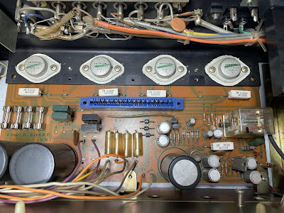
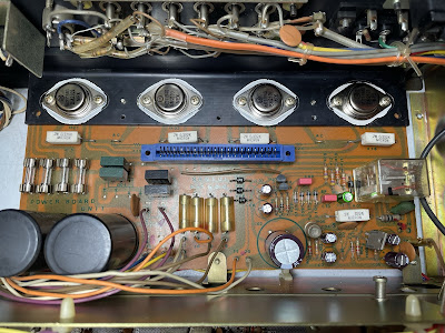
The Sansui 661 is a service-friendly receiver. Each board has very good access and plenty of space to work on. The power circuit board F-1500A has a power supply circuit, protection circuit, the slot for the driver circuit board, and four power transistors. The driver circuit board is secured in the slot with a massive metal bracket.
The power supply circuit provides +13.2V DC for the Tuner board and +23.0V DC for the Pre-amplifier board. It also provides balanced power to the Power amplifier from the bridge rectifier and two filter capacitors C16/C17. This circuit has five aluminum electrolytic capacitors C02, C03, C04, C05, and C06. I replaced all of them with low impedance Nichicon UPM/UPW caps. Two large filter capacitors C16/C17 were tested in-circuit with Atlas ESR70 capacitance meter and have almost zero ESR. So, I didn't change them. In general, the filter capacitors rarely fail in vintage gears, and I usually don't replace them unless their ESR is high.
The protection circuit has five aluminum electrolytic capacitors C07, C08, C09, C10, and C11. Two of them, C10 and C11 are bipolar e-caps. I replaced the bipolar e-cap C09 with a high-quality film polyester WIMA MKS2 cap and another bipolar e-cap C11 with a new bipolar Nichicon UES cap. The other three aluminum e-caps C07, C08, and C09 were replaced with low impedance Nichicon UPW caps.
All electrolytic capacitors removed from this board were tested with Atlas ESR70 capacitance meter and results are below. Most of them are still within the factory capacitance tolerance except for the e-caps C09 and C11.
Test results on original capacitors removed from the power circuit board:
C02: rated capacitance – 1000uF, measured – 992uF, ESR – 0.12Ω, deviation: -1%
C03: rated capacitance – 47uF, measured – 52uF, ESR – 0.08Ω, deviation: +11%
C04: rated capacitance – 47uF, measured – 52uF, ESR – 0.11Ω, deviation: +11%
C05: rated capacitance – 100uF, measured – 106uF, ESR – 0.11Ω, deviation: +6%
C06: rated capacitance – 100uF, measured – 107uF, ESR – 0.31Ω, deviation: +7%
C07: rated capacitance – 33uF, measured – 38uF, ESR – 0.12Ω, deviation: +15%
C08: rated capacitance – 220uF, measured – 280uF, ESR – 0.11Ω, deviation: +27%
C09: rated capacitance – 1.0uF, measured – 1.4uF, ESR – 1.35Ω, deviation: +40%
C10: rated capacitance – 1.0uF, measured – 0.9uF, ESR – 2.3Ω, deviation: -10%
C11: rated capacitance – 47uF, measured – 58uF, ESR – 0.49Ω, deviation: +23%
Power Transistors
The original Hitachi power transistors 2SC1030 were removed, cleaned, and tested with Atlas DCA55 semiconductor analyzer. The measured DC current gain was in spec according to the datasheet. However, one transistor TR01 from the left channel was found leaky. The measured collector leakage current was 0.016mA which is substantial for Si transistor. A leakage current is expected to be less than 0.001mA for the Si transistor. I didn't have another 2SC1030 in stock and decided to replace all four power transistors with new ON Semiconductor MJ21194G transistors. The new transistors are specifically designed for high-power audio output and have excellent gain linearity. In addition, the total harmonic distortion measured on two matched pairs of MJ21194G transistors can be as low as 0.08% according to the datasheet. So, it is a perfect choice as a substitution transistor for the original Hitachi 2SC1030.
Below are the test results on the original and new power transistors. It should be noted that Atlas DCA55 semiconductor analyzer provides the accurate reading for DC current gain only on low power transistors. A high-power transistor requires a much higher collector current and collector-emitter voltage to accurately measure its current gain. However, it is still a very useful device for comparing transistors of a similar type for the purposes of gain matching or fault-finding.
Test results on original power transistors 2SC1030:
Left channel: TR01 (gain - 43, Vbe - 0.581V, leakage - 0.016mA), TR03 (gain - 35, Vbe - 0.598V)
Right channel: TR02 (gain - 43, Vbe - 0.574V), TR04 (gain - 46, Vbe - 0.591V)
Test results on new closely matched power transistors MJ21194G:
Left channel: TR01 (gain - 54, Vbe - 0.599V), TR03 (gain - 59, Vbe - 0.594V)
Right channel: TR02 (gain - 52, Vbe - 0.597V), TR04 (gain - 54, Vbe - 0.601V)
Leaky transistor TR01 from the left channel - substantial leakage current
Power Circuit Board F-1500A - before and after
Driver Circuit Board F-1499A
As I mentioned earlier the driver circuit board in Sansui 661 can be easily removed from the slot for service. This board has two low leakage electrolytic capacitors C01/C02 installed in the signal path and six aluminum e-caps C05/C06, C09/C10, C13/C14. I replaced the low leakage e-caps with high-quality film polyester WIMA MKS2 caps. And six aluminum e-caps were replaced with low impedance Nichicon UPW caps.
Test results on original capacitors removed from the driver circuit board:
C01: rated capacitance – 0.47uF, measured – 0.57uF, ESR – N/A, deviation: +21%
C02: rated capacitance – 0.47uF, measured – 0.56uF, ESR – N/A, deviation: +19%
C05: rated capacitance – 220uF, measured – 288uF, ESR – 0.11Ω, deviation: +31%
C06: rated capacitance – 220uF, measured – 275uF, ESR – 0.09Ω, deviation: +25%
C09: rated capacitance – 33uF, measured – 36uF, ESR – 0.16Ω, deviation: +9%
C10: rated capacitance – 33uF, measured – 37uF, ESR – 0.22Ω, deviation: +12%
C13: rated capacitance – 100uF, measured – 104uF, ESR – 0.07Ω, deviation: +4%
C14: rated capacitance – 100uF, measured – 110uF, ESR – 0.04Ω, deviation: +10%
Four NPN transistors TR05, TR06, TR09, and TR10 installed on the driver circuit board are Sony 2SC1124. The current gain in the 2SC1124 transistor degrades with age. The modern substitution is a Fairchild KSC2690A transistor. I replaced two original Sony transistors TR05 and TR06 with KSC2690A to prevent any issues in the future. Watch the pinout on replacement transistors. The original transistor is EBC and the new one is ECB.
I didn't replace the other two Sony transistors TR09 and TR10 due to the difference in packaging between 2SC1124 and KSC2690A. The packaging type of the original Sony 2SC1124 is TO-202 while the Fairchild KSC2690A transistor has a packaging type of TO-126. It would be impossible to provide a good thermal contact between two pairs of transistors TR09/TR07 and TR10/TR08 which is critical to compensate for any temperature drift under normal operating conditions. So, I left them alone.
Two PNP transistors TR11 and TR12 installed on the driver circuit board are 2SA706. This transistor is also known for current gain deterioration with age. I replaced both of them with Fairchild KSA1220A transistors. Again, watch the pinout on replacement transistors. The original transistor is EBC and the new one is ECB.
I also replaced four green dot diodes D01 thru D04 on this board with Fairchild 1N4148 diodes. The original diodes DS-430 are still okay but their reliability is in question. So, I usually prefer to replace them to avoid any issues in the future.
Driver Circuit Board F-1499A - before and after
Pre-Amplifier Circuit Board F-1501
The pre-amplifier circuit board F-1501 has two solid tantalum C01/C02, four low leakage C15/C16, C25/C26, and four aluminum C09/C10, C601/C602 electrolytic capacitors. The tantalum and low leakage e-caps are installed in the signal path. I replaced them with high-quality film polyester WIMA MKS2 caps. The remaining four aluminum capacitors were replaced with low impedance Nichicon UPW caps.
Test results on original capacitors removed from the pre-amplifier circuit board:
C01: rated capacitance – 1.5uF, measured – 1.5uF, ESR – 6.2Ω, deviation: 0%
C02: rated capacitance – 1.5uF, measured – 1.4uF, ESR – 6.6Ω, deviation: -7%
C09: rated capacitance – 100uF, measured – 112uF, ESR – 0.28Ω, deviation: +12%
C10: rated capacitance – 100uF, measured – 110uF, ESR – 0.29Ω, deviation: +10%
C15: rated capacitance – 0.47uF, measured – 0.43uF, ESR – N/A, deviation: -9%
C16: rated capacitance – 0.47uF, measured – 0.43uF, ESR – N/A, deviation: -9%
C25: rated capacitance – 0.47uF, measured – 0.47uF, ESR – N/A, deviation: 0%
C26: rated capacitance – 0.47uF, measured – 0.46uF, ESR – N/A, deviation: -2%
C601: rated capacitance – 100uF, measured – 117uF, ESR – 0.08Ω, deviation: +17%
C602: rated capacitance – 100uF, measured – 114uF, ESR – 0.08Ω, deviation: +14%
Six NPN transistors TR01 thru TR06 installed on this board are notorious 2SC1222 transistors. They usually get very noisy over time. I replaced them with modern low noise Fairchild KSC1845 transistors. The old and new transistors have the same pinout, i.e. ECB.
This point during the restoration is the best time to clean and lubricate all pots and switches located on this board. It is almost impossible to reach these pots and switches without removing this board once again. I used the DeoxIT 5% contact cleaner and DeoxIT FaderLube 5% spray for cleaning and lubricating, respectively.
Pre-Amplifier Circuit Board F-1501 - before and after
Dial, Meter, and Stereo Indicator Lamps
The Sansui 661 has three dial bulbs mounted inside the plastic illuminator box. This box can be easily released from the chassis if two small screws on the top of it are loosened. However, to reach these screws the front panel should be removed as well. I replaced the original incandescent bulbs with warm white LED lamps to maintain the original look and decrease heat.
Old incandescent dial bulbs
New warm white LED lamps installed
The signal meter lamp can be replaced even easier than the dial lamps. Just remove the plastic holder behind the meter and you would get plenty of space to reach the lamp. I replaced the original incandescent bulb for the signal meter with warm white LED lamp.
Plenty of space to replace a signal meter lamp - new warm white LED lamp installed
The stereo indicator bulb burned out in this unit. I replaced it with a new incandescent lamp.
New stereo indicator lamp installed
DC Offset and Bias Adjustments
The DC offset and bias adjustments are pretty straightforward and clearly described in the service manual. I adjusted the DC offset on each channel as close to zero volts as possible with the trimming resistors VR01 and VR02, respectively. The bias current was adjusted to ~19mA with the trimming resistors VR03 and VR04, respectively. Before adjustment, all trimming resistors were cleaned and lubricated with DeoxIT FaderLube 5% spray.
DC offset on the left and right channel after restoration
Bias current on the left and right channel after restoration
Output Power Test
At the end of my restoration, I loaded this receiver with a low inductance 8Ω/100W dummy resistor for each channel, connected my oscilloscope across the speaker terminals, and applied a sine-wave signal of 1kHz to the AUX jacks. The output sine-wave signal was perfectly symmetrical on both channels with no clipping up to 15.37 VRMS (left channel) and 15.10 VRMS (right channel). So, one can calculate that the output power is (15.37 x 15.37)/8=29.5W (left channel) and (15.10 x 15.10)/8=28.5W (right channel). The output power exceeds a factory specification for this model which is not too bad for 48 years old gear!
Output power test - meets and even exceeds a factory specification!
As usual, all the knobs and the front panel were gently cleaned in warm water with dish soap. The final result can be seen in the photos below. The receiver looks brand new again and sounds fantastic! Please watch a short demo video at the end of this post. Thank you for reading.
Sansui 661 - after restoration


welldone!claps,,,why didn't you change the pointer to lighted led pointer?will look very nice!
ReplyDeleteHi Paul, the original dial pointer in Sansui 661 has no light in it. It is just a painted metal needle. I left it alone to keep everything as close to original as possible.
DeleteIs there any fuse for lights only?
ReplyDeleteYes, it is a 5A fuse F05 on the power circuit board P-1500A.
DeleteThanks. Changed. Working now.
DeleteHi, I need to replace transistors TR01 through TR04 but I can not locat them on the board, would you please point them out for me? Thanks!
ReplyDeleteHi,
DeleteTransistors TR01 thru TR04 are output power transistors. They are mounted on a heat sink with Mica pads. The original power transistors installed in Sansui 661 are Hitachi 2SC1030 (see my description "Power Transistors", Power Circuit Board F-1500A).
you do the best overviews.
ReplyDeleteThank you!
DeleteHi. I've had a sansui 661 in storage for many years after a repair technician told me I need to replace a transistor. It's a Sanyo D3300. 9amp. Can you tell me what this does and is there a replacement? Couldn't find one online. Tested the unit today and sounds great even without the missing transistor.
ReplyDeleteAny help much appreciated. Peter.
Hi, just pulled my Sansui 661 out of storage. It still has a Sanyo D3300 transistor taped to the top after its last visit to the repair shop. Couldn't find a replacement online. Can you tell me what function this transistor has and if there is a replacement?
ReplyDeleteEverything seems to work fine, amazingly enough. Great sound. the volume control is a bit touchy tho'.
Any ideas would be much appreciated. Thanks. Peter
Peter, I believe you are talking about the voltage-regulating transistor TR06 (Sanyo 2SD330) located on the power supply board. This transistor provides +13.2V DC for the Tuner board. You can replace this transistor with MJE15030G. The replacement transistor has the same pinout as the original one.
DeleteGreat work! Thanks
ReplyDeletesorry, where can I find a new STEREO indicator bulb and what are the values of the characteristic parameters?
ReplyDeleteThanks.
Hi Mauro, the original stereo indicator lamp is 7V, 100mA. I usually order all lamps on this website www.wjoe.com. The owner provides the best price and service (no affiliation).
DeleteThanks Oleg!
DeleteWhat type of fuses did you use to replace the 4 internal fuses that are on the left side of the board (top side)?
ReplyDeleteThese are 4A quick-acting fuses. The Mouser P/N is 504-BK1-GMA-4-R
Delete