Unit: AM/FM Stereo Receiver
Manufacturer: Technics
Model: SA-600
SN: AJ9611F124
This is a receiver I restored some time ago and it comes from my private collection. I bought it a year ago from a kind older lady for a fair price and in
excellent cosmetic condition. The wood case, top grill, faceplate, and knobs
were almost flawless.
The
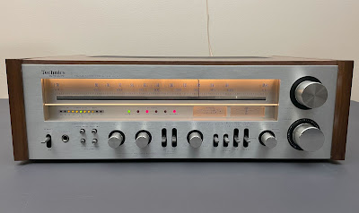
Technics SA-600 is a great mid-range receiver. It was manufactured from late
1978 to around 1979 and produces 70 watts per channel into 8 ohms with no more
than 0.04% total harmonic distortion. It has the classic Technics look with
dark insets around the knobs and the warm glow of the tuning dial. The build
quality is excellent.
A
very nice feature of the Technics SA-600 is its sliding wooden top, held by two small brackets. The top slides off once the two screws are removed, providing access to the inside of the receiver. However, the restoration of this Technics SA-600 was not an easy task, as I will explain further below.
Below are some photos I took during my restoration process,
complete with comments and recommendations. This receiver had no electronic issues, so the purpose of my restoration was to improve its general performance.
I did so by replacing the old electrolytic capacitors with new high-quality
capacitors and replacing the old transistors which were prone to create noise
or work improperly. I also refreshed the thermal compound between every power
transistor and heat sink and adjusted the factory settings to be sure that the
receiver would function well for the next twenty or so years.
The original dark blue electrolytic capacitors installed in this unit are low-quality Panasonic e-caps. Most of them have corrosive leads due to electrolyte leakage. I highly recommend replacing all electrolytic capacitors in vintage receivers because they are most susceptible to aging and degradation.
Dial Lamps
I replaced 3 old dial lamps with new incandescent bayonet base 6.3V, 0.25A bulbs. When replacing dial lamps, I typically install warm white LED lamps to maintain the receiver’s original look and decrease the production of heat. However, some models will have a more authentic look with original incandescent bulbs and this SA-600 is no exception.
Power Transistors
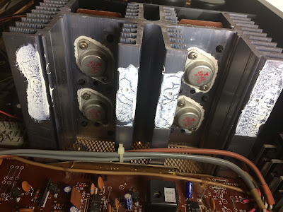
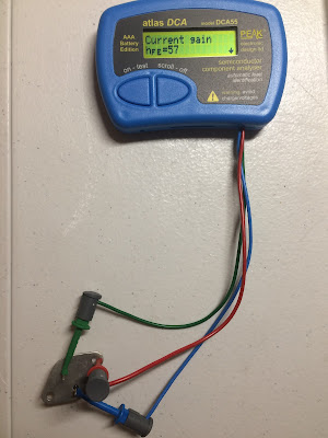
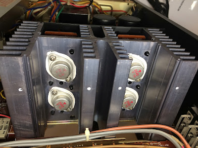
Four power transistors Q613 (x2), Q614 (x2) are mounted on a large heat sink. These transistors are very easy to remove and replace if the L-shaped supporting plate is removed from one side of the heat sink. All power transistors were removed, cleaned, and tested with Atlas DCA55 semiconductor analyzer. The measured DC current gain was in spec according to the datasheet. However, it should be noted that Atlas DCA55 semiconductor analyzer provides the accurate reading for DC current gain only on low-power transistors. A high-power transistor requires a much higher collector current and collector-emitter voltage to accurately measure its current gain. However, it is still a very useful device for comparing transistors of a similar type for the purposes of gain matching or fault-finding.
I applied a fresh thermal compound and replaced the old thermal pads with new Mica ones which is always a good idea when working on any vintage receiver. The old grease can frequently dry, causing the transistors to suffer from poor heat dissipation. This can result in overheating and the destruction of the device.
Heat sink with four power transistors - L-shaped supporting plate removed
PNP-type power transistors were removed, cleaned, and tested
NPN-type power transistors were removed, cleaned, and tested
Power transistors tested with Atlas DCA55 semiconductor analyzer
Power transistors mounted on a heat sink with new Mica pads and fresh thermal compound
Power Level Display Board (14170D)
The power level display (14170D) and display amplifier (14170C) circuit boards are mounted beneath the reflector plate. Due to a lack of space and engineering design, it was a bit tricky for me to remove these two boards, but being patient and documenting my steps assisted the process.
The power level display board only has 2 aluminum electrolytic capacitors: C809 and C810. I replaced them with high-reliability low-impedance Nichicon UPW caps.
Test results on original capacitors removed from the power level display circuit board:
C809: rated capacitance – 10uF, measured – 10uF, ESR – 1.64Ω, deviation: 0%
C810: rated capacitance – 10uF, measured – 10uF, ESR – 1.98Ω, deviation: 0%
Power level display board - before and after
Display Amplifier Board (14170C)
The display amplifier board has 9 aluminum electrolytic capacitors: C801, C802, C803, C804, C805, C806, C807, C811, and C812.
The e-caps C801, C802, and C811 were replaced with high-quality film polyester WIMA MKS2 caps. The remaining e-caps were replaced with low-impedance Nichicon UPW. The new Nichicon e-caps are longer by ~1mm than the original blue e-caps and I slightly bent them before mounting the insulation shield. A nonconducting stripe inside the metal shield prevents any electrical contact between different e-caps.
Test results on original capacitors removed from the display amplifier circuit board:
C801: rated capacitance – 1uF, measured – 1uF, ESR – 2.2Ω, deviation: 0%
C802: rated capacitance – 1uF, measured – 1.1uF, ESR – 2.4Ω, deviation: +10%
C803: rated capacitance – 10uF, measured – 9uF, ESR – 2.1Ω, deviation: -10%
C804: rated capacitance – 10uF, measured – 9uF, ESR – 2.2Ω, deviation: -10%
C805: rated capacitance – 2.2uF, measured – 2.3uF, ESR – 2.5Ω, deviation: +5%
C806: rated capacitance – 2.2uF, measured – 2.2uF, ESR – 2.8Ω, deviation: 0%
C807: rated capacitance – 10uF, measured – 11uF, ESR – 1.98Ω, deviation: +10%
C811: rated capacitance – 0.47uF, measured – 0.54uF, ESR – N/A, deviation: +15%
C812: rated capacitance – 33uF, measured – 35uF, ESR – 1.22Ω, deviation: +6%
Display amplifier board - before and after
This point during the restoration is the best time to clean and lubricate the speaker switches (main and remote) and two pots (bass and treble). I would strongly recommend doing it before mounting back the power level display and display amplifier boards. It is impossible to reach these switches and pots without removing those two boards once again. I used the DeoxIT 5% contact cleaner and DeoxIT FaderLube 5% spray for cleaning and lubricating, respectively.
The power level display and display amplifier boards are removed - it's the best time to clean and lubricate the speaker switches and two pots
Main Amplifier & Power Supply Board (14170A)
The power supply, main amplifier, tone control, and speaker protection circuits are all located on the same circuit board. This board is fairly simple to work with, excluding the speaker protection circuit which is located under the small board with fuses and near two large filter capacitors.
The main amplifier & power supply board has 2 low-leakage capacitors (C601, C602) installed in the signal path, one low-leakage capacitor C902 installed in the speaker protection circuit, one bi-polar e-cap C904 also installed in the speaker protection circuit, and 18 aluminum electrolytic capacitors (C520, C611, C612, C613, C614, C615, C616, C631, C632, C633, C634, C705, C706, C707, C708, C752, C903, and C905).
Two original low-leakage capacitors installed in the signal path were replaced with modern low-leakage Nichicon UKL caps. A low-leakage e-cap C902 was also replaced with a new low-leakage Nichicon UKL cap. The original bi-polar capacitor C904 was replaced with a new bi-polar Nichicon UEP cap. The remaining aluminum e-caps were replaced with low-impedance Nichicon UPW/UPM caps.
Note that 2 e-caps (C632 and C904) have a deviation from the nominal capacitance of more than 30%. Also, the original e-cap C902 installed in the speaker protection circuit has an extremely large ESR of over 40Ω!
Original e-cap C902 - extremely large ESR
Test results on original capacitors removed from the main amplifier & power supply circuit board:
C520: rated capacitance – 100uF, measured – 110uF, ESR – 0.59Ω, deviation: +10%
C601: rated capacitance – 4.7uF, measured – 4.6uF, ESR – 1.01Ω, deviation: -2%
C602: rated capacitance – 4.7uF, measured – 4.4uF, ESR – 0.86Ω, deviation: -6%
C611: rated capacitance – 33uF, measured – 35uF, ESR – 1.16Ω, deviation: +6%
C612: rated capacitance – 33uF, measured – 36uF, ESR – 1.26Ω, deviation: +9%
C613: rated capacitance – 47uF, measured – 46uF, ESR – 1.06Ω, deviation: -2%
C614: rated capacitance – 47uF, measured – 47uF, ESR – 0.89Ω, deviation: 0%
C615: rated capacitance – 100uF, measured – 105uF, ESR – 0.11Ω, deviation: +5%
C616: rated capacitance – 100uF, measured – 107uF, ESR – 0.11Ω, deviation: +7%
C631: rated capacitance – 100uF, measured – 110uF, ESR – 0.13Ω, deviation: +10%
C632: rated capacitance – 33uF, measured – 16uF, ESR – 1.33Ω, deviation: -52%
C633: rated capacitance – 330uF, measured – 379uF, ESR – 0.02Ω, deviation: +15%
C634: rated capacitance – 220uF, measured – 262uF, ESR – 0.04Ω, deviation: +19%
C705: rated capacitance – 470uF, measured – 482uF, ESR – 0.02Ω, deviation: +3%
C706: rated capacitance – 47uF, measured – 49uF, ESR – 0.31Ω, deviation: +4%
C707: rated capacitance – 220uF, measured – 230uF, ESR – 0.01Ω, deviation: +5%
C708: rated capacitance – 220uF, measured – 230uF, ESR – 0.02Ω, deviation: +5%
C752: rated capacitance – 470uF, measured – 506uF, ESR – 0.03Ω, deviation: +8%
C902: rated capacitance – 2.2uF, measured – 1.8uF, ESR – >40Ω, deviation: -18%
C903: rated capacitance – 100uF, measured – 109uF, ESR – 0.46Ω, deviation: +9%
C904: rated capacitance – 220uF, measured – 304uF, ESR – 0.61Ω, deviation: +38%
C905: rated capacitance – 100uF, measured – 86uF, ESR – 0.21Ω, deviation: -14%
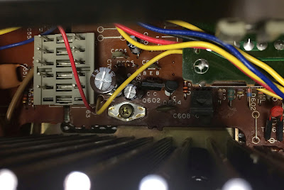
I recommend paying attention to filtering capacitor C520 on this board if you need to service it. The schematic shows this position as 33uF/16V despite the original capacitor being 100uF/6.3V. I replaced this cap with another one rated at 100uF/16V.
C520 is between transistor Q602 and the ground screw
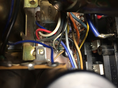
The speaker protection circuit is part of the main amplifier & power supply circuit board. This is another tricky place to work on due to the lack of space. I had to remove a small board with fuses and the supporting plate, which helps hold two large filter caps but still had very limited access to all electronic components located here.
The speaker protection circuit is under this small board with fuses next to the power transformer
The speaker protection circuit - before servicing (the small board with fuses was removed)
Speaker protection circuit - after servicing
The original protection relay was replaced with a new Omron relay to improve overall reliability.
I also noticed that the 3 original carbon resistors (R623, R624, R650) installed on this board are showing signs of overheating. I replaced them with new KOA Speer metal film resistors.
Main amplifier & power supply circuit board - before and after
FM/AM Tuner and Equalizer Amplifier Board (14210A)
An FM/AM tuner and equalizer amplifier circuits are assembled on the same circuit board 14210A.
This board has 11 low-leakage capacitors (C304, C305, C306, C313, C314, C318, C319, C401, C402, C411, C412) and 16 aluminum electrolytic capacitors (C19, C104, C106, C110, C114, C115, C202, C203, C206, C302, C315, C316, C320, C403, C404, and C413).
All original low-leakage capacitors with a nominal capacitance of 1uF and below were replaced with film polyester WIMA and Kemet capacitors. Three ordinary aluminum e-caps (C106, C115, C206) were also replaced with film polyester WIMA capacitors. The low-leakage capacitors (C318, C319, C401, C402) with a nominal capacitance of 3.3uF were replaced with modern low-leakage Nichicon UKL caps. And, the remaining aluminum electrolytic capacitors were replaced with low-impedance Nichicon UPW/UPM caps.
Note that 2 e-caps (C313 and C314) have a deviation from the nominal capacitance of more than 80%! Also, the original e-cap C402 installed in the input signal path has a relatively large ESR of 8.4Ω.
Test results on original capacitors removed from the FM/AM tuner & equalizer amp circuit board:
C19: rated capacitance – 330uF, measured – 341uF, ESR – 0.36Ω, deviation: +3%
C104: rated capacitance – 3.3uF, measured – 3.2uF, ESR – 2.8Ω, deviation: -3%
C106: rated capacitance – 1uF, measured – 1.1uF, ESR – 1.92Ω, deviation: +10%
C110: rated capacitance – 10uF, measured – 10uF, ESR – 2.4Ω, deviation: 0%
C114: rated capacitance – 330uF, measured – 371uF, ESR – 0.54Ω, deviation: +12%
C115: rated capacitance – 0.47uF, measured – 0.51uF, ESR – N/A, deviation: +9%
C202: rated capacitance – 33uF, measured – 35uF, ESR – 1.1Ω, deviation: +6%
C203: rated capacitance – 3.3uF, measured – 3.3uF, ESR – 3.6Ω, deviation: 0%
C206: rated capacitance – 0.47uF, measured – 0.51uF, ESR – N/A, deviation: +9%
C302: rated capacitance – 47uF, measured – 51uF, ESR – 0.71Ω, deviation: +9%
C304: rated capacitance – 0.22uF, measured – 0.21uF, ESR – N/A, deviation: -5%
C305: rated capacitance – 0.47uF, measured – 0.45uF, ESR – N/A, deviation: -4%
C306: rated capacitance – 0.47uF, measured – 0.42uF, ESR – N/A, deviation: -11%
C313: rated capacitance – 0.33uF, measured – 0.62uF, ESR – N/A, deviation: +88%
C314: rated capacitance – 0.33uF, measured – 0.63uF, ESR – N/A, deviation: +91%
C315: rated capacitance – 47uF, measured – 51uF, ESR – 0.81Ω, deviation: +9%
C316: rated capacitance – 3.3uF, measured – 3.2uF, ESR – 2.6Ω, deviation: -3%
C318: rated capacitance – 3.3uF, measured – 3.3uF, ESR – 2.1Ω, deviation: 0%
C319: rated capacitance – 3.3uF, measured – 3.1uF, ESR – 2.4Ω, deviation: -6%
C320: rated capacitance – 3.3uF, measured – 3.4uF, ESR – 2.9Ω, deviation: +3%
C401: rated capacitance – 3.3uF, measured – 2.8uF, ESR – 4.8Ω, deviation: -15%
C402: rated capacitance – 3.3uF, measured – 2.7uF, ESR – 8.4Ω, deviation: -18%
C403: rated capacitance – 100uF, measured – 97uF, ESR – 0.86Ω, deviation: -3%
C404: rated capacitance – 100uF, measured – 108uF, ESR – 0.48Ω, deviation: +8%
C411: rated capacitance – 1uF, measured – 0.9uF, ESR – 4.7Ω, deviation: -10%
C412: rated capacitance – 1uF, measured – 0.9uF, ESR – 4.7Ω, deviation: -10%
C413: rated capacitance – 220uF, measured – 246uF, ESR – 0.02Ω, deviation: +12%
The voltage regulating transistor Q751 (2SC1398), located behind the volume potentiometer, is mounted on a heat sink. This transistor is running hot under normal operating conditions. Some PCB discoloration can be seen around a heat sink. I decided to refresh the thermal compound between this transistor and the heat sink. To my surprise, I found no old thermal grease when I removed the heat sink from this transistor. The back side of the heat sink was completely dry. What the heck?! Did the technician forget to apply thermal grease or did it dry out? I tested this transistor with Atlas DCA55 semiconductor analyzer and it was Okay. I applied a fresh thermal paste to the transistor and mounted it back onto the heat sink to make its life easier.
Transistor Q751 mounted on a heat sink - no old thermal grease was found
FM/AM tuner and equalizer amplifier board - before and after
Bias Adjustment
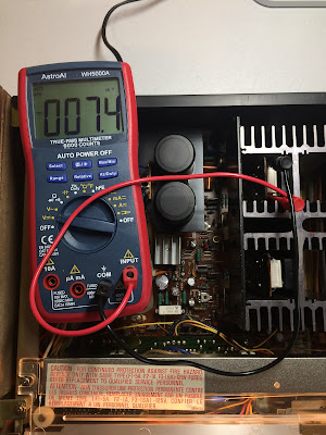
Finally, I checked and adjusted the Bias on the power amplifier. This procedure is straightforward and clearly described in a service manual. The bias was adjusted to ~7.4mV on each channel.
Bias on the left and right channels after restoration
Filter Capacitors
I performed an in-circuit test on two main filter capacitors with an Atlas ESR70 capacitance meter. Both caps are still within the factory capacitance tolerance and have very low ESR. So, I didn't change them. In general, the filter capacitors rarely fail in vintage gears, and I usually don't replace them unless their ESR is high.
In-circuit test on two filter capacitors - both are still in spec
C701: rated capacitance – 15000uF, measured – 14520uF, ESR – 0.07Ω, deviation: -3%
C702: rated capacitance – 15000uF, measured – 15070uF, ESR – 0.09Ω, deviation: +1%
Output Power Test
The final output power test was performed at the end of my restoration. The receiver was loaded with a low inductance 8Ω/100W dummy resistor for each channel. The oscilloscope was connected across the speaker terminals and a sine-wave signal of 1kHz was applied to the AUX jacks. The output sine-wave signal was perfectly symmetrical on both channels with no clipping up to 24.27 VRMS (left channel) and 24.59 VRMS (right channel). It corresponds to the output power of 73.6W on the left channel and 75.6W on the right channel.
Output power test
All the knobs and the front panel were cleaned with dish soap and slightly polished with the Mothers Mag & Aluminum polish paste. All controls have been cleaned with DeoxIT 5% contact cleaner and lubricated with DeoxIT FaderLube 5% spray.
Now, the final result is amazing! The receiver looks and works great, and I enjoy listening to it. Please watch a short demo video at the end of this post. Thank you for reading.
Demo video after repair & restoration




_before%20servicing.jpg)
_after%20servicing.jpg)
_before%20%20servicing.jpg)
_after%20%20servicing.jpg)




_before%20servicing.jpg)
_after%20servicing.jpg)





Hello Oleg. Wow! Great article. Thanks! I have the same receiver that I'm trying to fix for my girlfriend. There is a lot of static on the right channel speaker outputs and the volume is very low as compared to the left channel. Can you point me in the right direction please?
ReplyDeleteHello, I would strongly recommend you to start by cleaning all pots and switches with DeoxIT. Most problems in vintage receivers are related with dirty pots and/or oxidized contacts in switches. Unfortunately, this receiver is not the easiest one for cleaning. I remember I had a lot of trouble cleaning the SELECTOR switch. Do you have a multimeter?
DeleteHi Oleg. Yes I do have a multimeter.
DeleteHi I have a sa-600 and was going to attempt this project. What tools and products do you recommend. Thank for your time
ReplyDeleteI’ve one of these in absolute dead mint. Out in my roundtuit shed. First one was the Fisher 400. Couldn’t resist restoration of that one first.
ReplyDeleteBack to your SA 600, no shoot on sight transistors used in this model? Haven’t bothered pulling up the scat yet. Nice job other than I always without exception replace bias and DC offset trimmers.
Hi Oleg.
ReplyDeleteWhat brand and where did you purchase the warm white LED's you used in your SA-600? I recently purchased a set of warm white LED's from Just Audio/Stereo Lamps for my SA-700 and they do not look any crisper or brighter than the original incandescent bulbs. Do you have any suggestions or possible solutions for me? Thanks!
Hello,
DeleteIn this particular unit, I replaced 3 original dial lamps with new incandescent bayonet base 6.3V, 0.25A lamps. I tried to install warm white LED lamps but didn't like how they look on this model. But in general, I usually order LED lamps on this website www.wjoe.com. The owner provides the best price and service (no affiliation).
Hi! Fantastic write up, used it to recap my new (to me) SA600 :)
ReplyDeleteOne issue I'm still encountering is the power level display lights arent working, but everything else is 100%.
Any thoughts on where I should start to resolve this?
Thank you
Hi, have you cleaned all the controls? Especially the power display switch? On my SA-600, all the switches were very dirty with oxidized contacts.
DeleteGreat right up as usual. I have 2 600's. I just picked up a 600A dark face. You're correct, they are not easy to work on. Getting to all the controls to clean is not easy. I have an issue with it not getting stereo in FM. I've tried adjusting VR302, but no difference. I'll need to dig in a little more. But other than that, it's in great shape and sounds great.
ReplyDeleteHello, the VR302 trimmer is used for FM stereo separation alignment. You need to adjust the position of the VR301 trimmer. Refer to the service manual, page 4, item 10.
DeleteThanks, I did try to adjust VR301 as well. But I don't have a SG that works at FM signal ranges to really do a complete FM alignment correctly. I'll have to look into getting one. I love following your posts. They have helped save me time on an SX-727 and 828 that I've recently worked on.
DeleteWow what an article to read for a vintage music fan that has very limited electronic skills! Thank you
ReplyDelete