Unit: AM/FM Stereo Receiver
Manufacturer: Marantz
Model: 2215
SN: 7972
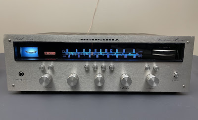
Today I'm showcasing a Marantz 2215 vintage receiver that came in for restoration. This model was manufactured from 1971 to 1973. It produces 15 watts per channel into 8 ohms with no more than 0.9% total harmonic distortion. The retail price in 1971 was $199.00 (Ref. Stereo Review, November 1971, page 43). The optional walnut veneer cabinet for this model is WC-22/WC-42.
An early version of the Marantz 2215 features a champagne engraved faceplate. Later versions have a brushed metal faceplate. I believe the champagne engraved faceplate was only installed in 1971. And in 1972, the champagne faceplate was replaced with a brushed faceplate to reduce the cost.
I serviced another 2215 a few years ago with serial number 3835 and this receiver has the original champagne engraved faceplate. It was manufactured in 1971 according to the factory stamp on the chassis. This particular unit with serial number 7972 was manufactured in 1972 and has a brushed metal faceplate.
Power Supply Board (P800)
The power supply board has 7 aluminum electrolytic capacitors: C803, C804, C805, C806, C808, C809, and C810. I replaced all capacitors on this board with low impedance Nichicon UPW/UPM caps.
The original e-caps were tested with an Atlas ESR70 capacitance meter; the results are below.
Test results on original capacitors removed from the power supply board:
C803: rated capacitance – 330uF, measured – 383uF, ESR – 0.04Ω, deviation: +16%
C804: rated capacitance – 470uF, measured – 492uF, ESR – 0.05Ω, deviation: +5%
C805: rated capacitance – 470uF, measured – 553uF, ESR – 0.08Ω, deviation: +18%
C806: rated capacitance – 47uF, measured – 55uF, ESR – 0.24Ω, deviation: +17%
C808: rated capacitance – 47uF, measured – 57uF, ESR – 0.24Ω, deviation: +21%
C809: rated capacitance – 100uF, measured – 121uF, ESR – 0.11Ω, deviation: +21%
C810: rated capacitance – 470uF, measured – 563uF, ESR – 0.04Ω, deviation: +20%
To improve the reliability of the power supply board, I also replaced all semiconductors.
The original regulating transistor 2SC1213A installed in position H802 was replaced with a new Fairchild KSC2383YTA transistor.
Two original diodes H804, H805, and H808 were replaced with the modern fast recovery rectifiers UF4005.
Finally, the original Zener diode BZ-120 installed in position H806 was replaced with a new OnSemi 1N4742A.
Power supply board - before and after
Tone Amplifier Board (P500)
The tone amplifier board has 4 low leakage e-caps (C505, C506, C513, C514) installed in the signal path, and 7 aluminum electrolytic capacitors (C503, C504, C509, C510, C511, C512, C515).
The original low leakage e-caps were replaced with high-quality film polyester WIMA MKS2 caps. Two ordinary aluminum e-caps (C503, C504) installed in the signal path were replaced with modern low leakage Nichicon UKL caps to reduce the noise generated in the circuit. And the remaining aluminum e-caps were replaced with low impedance Nichicon UPW caps.
Most of the original electrolytic capacitors from this board are outside the capacitance tolerance of +/- 20%. The original e-cap C510 has drifted from its nominal capacitance of 100uF to 295uF, i.e. the deviation is 195%!
Test results on original capacitors removed from the tone amplifier board:
C503: rated capacitance – 4.7uF, measured – 6.2uF, ESR – 1.61Ω, deviation: +32%
C504: rated capacitance – 4.7uF, measured – 6.1uF, ESR – 1.48Ω, deviation: +30%
C505: rated capacitance – 1uF, measured – 1uF, ESR – 7.1Ω, deviation: 0%
C506: rated capacitance – 1uF, measured – 1uF, ESR – 5.8Ω, deviation: 0%
C509: rated capacitance – 100uF, measured – 145uF, ESR – 0.27Ω, deviation: +45%
C510: rated capacitance – 100uF, measured – 295uF, ESR – 0.38Ω, deviation: 195% (!)
C511: rated capacitance – 10uF, measured – 12uF, ESR – 0.66Ω, deviation: +20%
C512: rated capacitance – 10uF, measured – 11uF, ESR – 0.69Ω, deviation: +10%
C513: rated capacitance – 0.47uF, measured – 0.73uF, ESR – N/A, deviation: +55%
C514: rated capacitance – 0.47uF, measured – 0.68uF, ESR – N/A, deviation: +45%
C515: rated capacitance – 100uF, measured – 123uF, ESR – 0.12Ω, deviation: +23%
The NPN transistor 2SC458LG installed on this board in positions H501 thru H506 has a bad reputation as a potential source of noise. I replaced all 2SC458LGs with a modern low-noise Fairchild KSC1845 transistor. Watch the pinout on replacement transistors. The original transistor is BCE and the new one is ECB.
Tone amplifier board - before and after
Phono Amplifier Board (P900)
The phono amplifier board has 2 low leakage e-caps (C901, C902) installed in the input signal path, 2 solid tantalum capacitors (C905, C906), and 3 aluminum electrolytic capacitors (C909, C910, C919).
The original low leakage e-caps were replaced with film polyester WIMA MKS2 caps. Two solid tantalum capacitors were replaced with modern low leakage Nichicon UKL caps. And the remaining aluminum e-caps were replaced with low impedance Nichicon UPW/UPM caps.
Test results on original capacitors removed from the phono amplifier board:
C901: rated capacitance – 1uF, measured – 1uF, ESR – 3.41Ω, deviation: 0%
C902: rated capacitance – 1uF, measured – 1uF, ESR – 1.86Ω, deviation: 0%
C905: rated capacitance – 22uF, measured – 25uF, ESR – 0.62Ω, deviation: +14%
C906: rated capacitance – 22uF, measured – 26uF, ESR – 0.51Ω, deviation: +18%
C909: rated capacitance – 47uF, measured – 66uF, ESR – 0.48Ω, deviation: +40%
C910: rated capacitance – 47uF, measured – 65uF, ESR – 0.51Ω, deviation: +38%
C919: rated capacitance – 100uF, measured – 126uF, ESR – 0.18Ω, deviation: +26%
The original Toshiba 2SC1000 transistor installed in positions H901 to H904 often generates static noise in the circuit. I replaced all 2SC1000 transistors on this board with the modern low noise Fairchild KSC1845. The KSC1845 transistor has the same pinout as the Toshiba 2SC1000.
The original 2SC458LG transistor installed at positions H905 and H906 is also known to be a potential source of the noise. I replaced all 2SC458LGs with modern low noise Fairchild KSC1845 transistors. Watch the pinout on replacement transistors. The original transistor is BCE and the new one is ECB.
Phono amplifier board - before and after
Power Amplifier Board (P700)
The power amplifier board has 2 low leakage e-caps (C701, C702) installed in the input signal path, and 12 aluminum electrolytic capacitors (C703, C704, C707, C708, C709, C710, C711, C712, C715, C716, C717, C718).
The original low leakage capacitors were replaced with film polyester WIMA MKS2 caps. The ordinary aluminum e-caps (C711 and C712) coupled between a pre-driver H701 (H702) and driver H703 (H704) transistor were replaced with modern low leakage Nichicon UKL caps to reduce the noise. The remaining aluminum capacitors were replaced with low impedance Nichicon UPW caps.
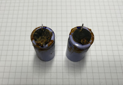
Two filter capacitors (C703 and C704) were glued to the board at the factory. I am not sure what type of glue was used, but it badly affected those capacitors. The rubber sealing completely dried out and has many microcracks. The positive terminal on each capacitor was rotted. Before installing new capacitors, I carefully removed the old adhesive from the board and cleaned the surrounding area with isopropyl alcohol.
Rotted leads on original filter capacitors C703 & C704
Test results on original capacitors removed from the power amplifier board:
C701: rated capacitance – 0.47uF, measured – 0.76uF, ESR – N/A, deviation: +62%
C702: rated capacitance – 0.47uF, measured – 0.61uF, ESR – N/A, deviation: +30%
C703: rated capacitance – 220uF, measured – N/A, positive terminal is rotted
C704: rated capacitance – 220uF, measured – N/A, positive terminal is rotted
C707: rated capacitance – 47uF, measured – 49uF, ESR – 0.16Ω, deviation: +4%
C708: rated capacitance – 47uF, measured – 48uF, ESR – 0.22Ω, deviation: +2%
C709: rated capacitance – 47uF, measured – 50uF, ESR – 0.18Ω, deviation: +6%
C710: rated capacitance – 47uF, measured – 50uF, ESR – 0.21Ω, deviation: +6%
C711: rated capacitance – 10uF, measured – 11uF, ESR – 0.92Ω, deviation: +10%
C712: rated capacitance – 10uF, measured – 12uF, ESR – 0.84Ω, deviation: +20%
C715: rated capacitance – 100uF, measured – 114uF, ESR – 0.34Ω, deviation: +14%
C716: rated capacitance – 100uF, measured – 105uF, ESR – 0.32Ω, deviation: +5%
C717: rated capacitance – 22uF, measured – 26uF, ESR – 0.26Ω, deviation: +18%
C718: rated capacitance – 22uF, measured – 27uF, ESR – 0.34Ω, deviation: +23%
All original trimming resistors (R723, R724, R729, R730) were replaced with new Bourns potentiometers. One original trimming resistor (R723) turned out to be faulty (open circuit).
Power amplifier board - before and after
Power Transistors
The original power transistors were removed, cleaned, and tested with Atlas DCA55 semiconductor analyzer. The measured DC current gain on all transistors met the specifications in the datasheet. I mounted all the transistors back on the heat sink and applied fresh thermal paste. The old thermal pads were also replaced with new Mica ones.
FM Front End & AM Tuner Board (P100)
I didn't notice any problem with the tuner section in this receiver during the initial evaluation. However, due to the fact that all the controls in this unit were very dirty, it was quite difficult to pinpoint any particular issue. After I finished servicing all boards except the tuner section, I cleaned all the controls and tested the tuner again. I have noticed that the FM reception on this unit is not perfect. This could be improved upon the alignment of the tuner, but I chose to service the tuner section in this unit anyway due to the presence of many blue Panasonic e-caps. These capacitors do not age well and often deviate greatly from their capacitance rating. And, as you will see later, it was worth doing.
Please note that the FM Front End & AM tuner board cannot be serviced without being disassembled from the chassis. Make sure you have a new dial cord and be prepared to re-string the tuner.
The FM Front End & AM tuner board has 13 aluminum electrolytic capacitors (C105, C108, C112, C114, C118, C119, C121, C122, C128, C130, C131, C154, and C156). Nine of them are notorious blue Panasonic e-caps. I replaced all electrolytic capacitors on this board with low impedance Nichicon UPW caps. Note, that the e-cap C156 is soldered on the back (foil) side of the PCB.
The e-cap C156 is soldered on the back (foil) side
As can be seen below, all blue Panasonic capacitors are outside the capacitance tolerance of +/- 20%. Two of them (C105 & C108) drifted from their nominal capacitance by more than 100%!
Test results on original capacitors removed from the FM Front End & AM tuner board:
C105: rated capacitance – 10uF, measured – 25uF, ESR – 2.6Ω, deviation: +150% (!)
C108: rated capacitance – 10uF, measured – 34uF, ESR – 9.9Ω, deviation: +240% (!)
C112: rated capacitance – 10uF, measured – 14uF, ESR – 0.84Ω, deviation: +40%
C114: rated capacitance – 100uF, measured – 117uF, ESR – 0.21Ω, deviation: +17%
C118: rated capacitance – 10uF, measured – 15uF, ESR – 1.43Ω, deviation: +50%
C119: rated capacitance – 10uF, measured – 15uF, ESR – 1.18Ω, deviation: +50%
C121: rated capacitance – 10uF, measured – 14uF, ESR – 0.93Ω, deviation: +40%
C122: rated capacitance – 10uF, measured – 16uF, ESR – 1.17Ω, deviation: +60%
C128: rated capacitance – 220uF, measured – 222uF, ESR – 0.18Ω, deviation: +1%
C130: rated capacitance – 10uF, measured – 14uF, ESR – 0.77Ω, deviation: +40%
C131: rated capacitance – 10uF, measured – 14uF, ESR – 0.95Ω, deviation: +40%
C154: rated capacitance – 33uF, measured – 42uF, ESR – 0.62Ω, deviation: +27%
C156: rated capacitance – 220uF, measured – 258uF, ESR – 0.11Ω, deviation: +17%
The original e-cap C108 - the nominal capacitance is 10uF but the measured is 34uF
FM Front End & AM tuner board -before and after
FM IF Amplifier & Detector Unit (P200)
This board has 7 aluminum electrolytic capacitors: C203, C206, C210, C218, C225, C228, and C231. All of them were replaced with low impedance Nichicon UPW caps.
Again, all original e-caps from this board (blue Panasonic) drifted way out of the tolerance spec of +/- 20%. Some of them (C218, C228, and C231) drifted more than 100% from their nominal capacitance!
Test results on original capacitors removed from the FM IF amplifier & detector unit:
C203: rated capacitance – 10uF, measured – 17uF, ESR – 1.38Ω, deviation: +70%
C206: rated capacitance – 10uF, measured – 14uF, ESR – 0.82Ω, deviation: +40%
C210: rated capacitance – 10uF, measured – 17uF, ESR – 1.31Ω, deviation: +70%
C218: rated capacitance – 10uF, measured – 23uF, ESR – 2.4Ω, deviation: +130% (!)
C225: rated capacitance – 10uF, measured – 13uF, ESR – 0.96Ω, deviation: +30%
C228: rated capacitance – 10uF, measured – 28uF, ESR – 2.5Ω, deviation: +180% (!)
C231: rated capacitance – 10uF, measured – 45uF, ESR – 3.1Ω, deviation: +350% (!)
FM IF amplifier & detector unit - before and after
Muting Control & Meter Amplifier Unit (P300)
This board has only 3 aluminum electrolytic capacitors: C307, C308, and C309. I replaced them with low impedance Nichicon UPW/UHE caps.
Test results on original capacitors removed from the muting control & meter amplifier unit:
C307: rated capacitance – 33uF, measured – 36uF, ESR – 0.52Ω, deviation: +9%
C308: rated capacitance – 4.7uF, measured – 6.1uF, ESR – 1.81Ω, deviation: +30%
C309: rated capacitance – 10uF, measured – 12uF, ESR – 1.05Ω, deviation: +20%
Muting control & meter amplifier unit - before and after
MPX Stereo Decoding Amplifier Board (P400)
The MPX stereo decoding amplifier board has 3 low leakage e-caps (C432, C433, C434) and 13 aluminum electrolytic capacitors (C401, C402, C406, C408, C414, C415, C416, C417, C418, C419, C430, C431, and C435).
The original low leakage e-caps were replaced with WIMA MKS2 (C432, C433) and Kemet (C434) polyester film caps. The four ordinary aluminum e-caps (C417, C418, C430, C431) installed between the crosstalk canceling and buffer amplifiers were replaced with modern low leakage Nichicon UKL caps. The remaining aluminum e-caps were replaced with low impedance Nichicon UPW caps. Pay attention to the polarity of e-cap C414. The polarity on the silkscreen is backward!
Test results on original capacitors removed from the MPX stereo decoding amplifier board:
C401: rated capacitance – 10uF, measured – 13uF, ESR – 0.91Ω, deviation: +30%
C402: rated capacitance – 10uF, measured – 14uF, ESR – 1.14Ω, deviation: +40%
C406: rated capacitance – 10uF, measured – 13uF, ESR – 1.26Ω, deviation: +30%
C408: rated capacitance – 220uF, measured – 241uF, ESR – 0.14Ω, deviation: +10%
C414: rated capacitance – 33uF, measured – 41uF, ESR – 1.14Ω, deviation: +24%
C415: rated capacitance – 10uF, measured – 14uF, ESR – 3.1Ω, deviation: +40%
C416: rated capacitance – 10uF, measured – 11uF, ESR – 1.08Ω, deviation: +10%
C417: rated capacitance – 10uF, measured – 14uF, ESR – 1.12Ω, deviation: +40%
C418: rated capacitance – 10uF, measured – 16uF, ESR – 1.18Ω, deviation: +60%
C419: rated capacitance – 220uF, measured – 242uF, ESR – 0.22Ω, deviation: +10%
C430: rated capacitance – 10uF, measured – 18uF, ESR – 1.51Ω, deviation: +80%
C431: rated capacitance – 10uF, measured – 17uF, ESR – 1.58Ω, deviation: +70%
C432: rated capacitance – 0.47uF, measured – 0.57uF, ESR – N/A, deviation: +21%
C433: rated capacitance – 0.47uF, measured – 0.53uF, ESR – N/A, deviation: +13%
C434: rated capacitance – 0.1uF, measured – 0.12uF, ESR – N/A, deviation: +20%
C435: rated capacitance – 100uF, measured – 111uF, ESR – 0.32Ω, deviation: +11%
MPX stereo decoding amplifier board - before and after
Dial and Meter Lamps
The old incandescent lamps were replaced with warm white LED lamps to maintain the original look and decrease heat. The original incandescent lamp behind the meter was also replaced with a warm white LED lamp. The old yellowish vellum behind the dial scale was replaced with new heavyweight vellum paper.
The old stereo indicator and dial pointer lamps were replaced with new incandescent lamps.
Dial scale removed - original incandescent dial lamps
Audio Adjustments
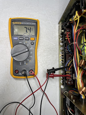
To adjust a bias, connect the multimeter between pins J713 and J715, and adjust the trimming resistor R729 until the multimeter reads ~7.5mV DC. For the other channel, connect the multimeter between J714 and J716, and adjust the trimming resistor R730 for the same reading.
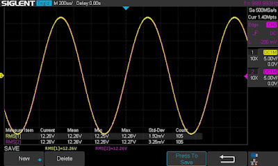
To adjust a clipping level, I connected my oscilloscope across the speaker terminals and applied a sine-wave signal of 1 kHz to the AUX jacks. The trimming resistor R723 was adjusted for equal and symmetrical clipping. For the other channel, the trimming resistor R724 was adjusted.
Bias on the left and right channels after restoration
Output Power Test
The final output power test was performed at the end of my restoration. The receiver was loaded with a low inductance 8Ω/100W dummy resistor for each channel. The oscilloscope was connected across the speaker terminals and a sine-wave signal of 1kHz was applied to the AUX jacks. The output sine-wave signal was perfectly symmetrical on both channels with no clipping up to 12.26 VRMS (left channel) and 12.26 VRMS (right channel). It corresponds to the output power of 18.8W on the left channel and 18.8W on the right channel.
Output power test
As usual, all the knobs and the face plate were gently cleaned in warm water with dish soap. All controls have been cleaned with DeoxIT 5% contact cleaner and lubricated with DeoxIT FaderLube 5% spray.
The final result can be seen in the photos below. Please watch a short demo video at the end of this post. Thank you for reading.
Marantz 2215 - after restoration


_before%20servicing.jpg)
_after%20servicing.jpg)
_before%20servicing.jpg)
_after%20servicing.jpg)
_before%20servicing.jpg)
_after%20servicing.jpg)

_before%20servicing.jpg)
_after%20servicing.jpg)
_C156.jpg)
_C108.jpg)
_before%20servicing.jpg)
_after%20servicing.jpg)
_before%20servicing.jpg)
_after%20servicing.jpg)
_before%20servicing.jpg)
_after%20servicing.jpg)
_before%20servicing.jpg)
_after%20servicing.jpg)


Hi,
ReplyDeleteThank you for this great and detail post. Very very educational.
I love your work and your passion. I wish i had your knowledge and your skills to restore my vintage audio collection. But I'm willing to learn, and your site is a great help for me in this process.
many thanks!!!
I too have found a nice example of the 2215. The large filter capacitor was actually open when it was first powered up. I have replaced most of the electrolytic now the question I would have is whether or not adding extra capacitance and a higher voltage on the, large filter cap could possibly stress the transformer and rectifier. I initially installed a 100V, 10,000uf And it’s certainly sounding good at this point. Do you think my concern is warranted with the extra capacitance?
ReplyDeleteThe original filter capacitor in Marantz 2215 is rated at 3,000uF/55V (C006). I wouldn't recommend installing a new capacitor larger than 30-40% above the nominal capacitance of C006. If you install a new filter cap with a nominal capacitance of 10,000uF then you can potentially stress a transformer and/or rectifier since it is more than 200% above the nominal capacitance of the original C006 cap. But it's ok to increase the nominal voltage of a new capacitor.
Deletehi Oleg, congrats on a beautiful restoration!
ReplyDeleteI have the same reciever, a 1971 2215 with engraved face. sadly the left output transistors are blown. do you know where to find replacements? ideall i would like to keep the original to66 case but am afraid they are obsolete.. wondering how you would approach this hurdle, thanks!
A few years ago, I repaired a Marantz 2215 receiver that was in very bad condition (three of the four original power transistors were burned out). I replaced the original 2SD315 transistors (TO-66 package) with new Fairchild KSC2073TU transistors (TO-220 package), and everything worked perfectly.
Delete