Unit: AM/FM Stereo Receiver
Manufacturer: Marantz
Model: 2230B
SN: UO10509
Today I'm showcasing a Marantz 2230B vintage receiver that came in for restoration. Marantz 2230B was manufactured from 1974 to 1977. It produces 30 watts per channel into 8 ohms with no more than 0.3% total harmonic distortion. The optional walnut veneer cabinet for this model is WC-22. The wood case gives the 2230B a very elegant look. I always recommend buying a wood case for all vintage Marantz lovers.
Marantz 2230B is a service-friendly receiver because of very good access to each PCB. According to the factory stamp on the chassis, this unit was manufactured in November 1976.
Power Supply Board (P800)
The regulated power supply has six aluminum e-caps C803, C804, C805, C808, C809, and C810. All of them were replaced with low-impedance and high-reliability Nichicon UPW caps. Those e-caps are designed for switching power supplies and can operate in the temperature range from -55 to +105 C. The original e-caps installed in vintage gears from the 70's have a maximum operating temperature of +85C.
The original e-caps were tested with an Atlas ESR70 capacitance meter and the results are below.
Test results on original capacitors removed from the power supply board:
C803: rated capacitance – 470uF, measured – 437uF, ESR – 0.04Ω, deviation: -7%
C804: rated capacitance – 470uF, measured – 322uF, ESR – 0.05Ω, deviation: -32%
C805: rated capacitance – 100uF, measured – 98uF, ESR – 0.06Ω, deviation: -2%
C808: rated capacitance – 3.3uF, measured – 3.6uF, ESR – 1.48Ω, deviation: +9%
C809: rated capacitance – 470uF, measured – 419uF, ESR – 0.04Ω, deviation: -11%
C810: rated capacitance – 1000uF, measured – 948uF, ESR – 0.02Ω, deviation: -5%
Both transistors (H805 & H806) and one rectifier diode H808 installed on this board were also replaced to improve the reliability of the power supply. The original transistor 2SD330 installed in position H805 was replaced with a new ON Semiconductor MJE15030G. Transistor 2SC945 installed in position H806 was replaced with a new Fairchild KSC945CYTA. The rectifier diode SIB-01-02 installed in position H808 was upgraded to a fast recovery rectifier UF4005.
The original trimming resistor R808 was replaced with a new Bourns potentiometer.
Power supply board - before and after
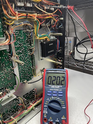
The DC voltage between pins J812 (+) and J811 (ground) was adjusted to +35V with the trimming resistor R808.
DC voltage between pins J812 and J811 under no signal condition
Tone Amplifier Board (PE01)
The tone amplifier board has six low leakage e-caps (CE05, CE06, CE19, CE20, CE21, CE22), two bi-polar capacitors (CE23, CE24), and three aluminum e-caps (CE03, CE04, CE25). The original low leakage e-caps CE19 and CE20 were replaced with high-quality film polyester WIMA caps. The other low leakage e-caps with higher rated capacitance were replaced with modern low leakage Nichicon UKL caps. Two bi-polar e-caps were replaced with film polyester WIMA caps. And, the remaining aluminum e-caps were replaced with low impedance Nichicon UPW/UPM caps.
Test results on original capacitors removed from the tone amplifier board:
CE03: rated capacitance – 10uF, measured – 13uF, ESR – 0.64Ω, deviation: +30%
CE04: rated capacitance – 10uF, measured – 12uF, ESR – 0.69Ω, deviation: +20%
CE05: rated capacitance – 4.7uF, measured – 4.5uF, ESR – 2.1Ω, deviation: -4%
CE06: rated capacitance – 4.7uF, measured – 4.8uF, ESR – 2.1Ω, deviation: +2%
CE19: rated capacitance – 1uF, measured – 1.1uF, ESR – 4.1Ω, deviation: +10%
CE20: rated capacitance – 1uF, measured – 1.0uF, ESR – 5.1Ω, deviation: 0%
CE21: rated capacitance – 3.3uF, measured – 3.0uF, ESR – 1.93Ω, deviation: -9%
CE22: rated capacitance – 3.3uF, measured – 3.1uF, ESR – 2.4Ω, deviation: -6%
CE23: rated capacitance – 1uF, measured – 1uF, ESR – 1.64Ω, deviation: 0%
CE24: rated capacitance – 1uF, measured – 1uF, ESR – 1.73Ω, deviation: 0%
CE25: rated capacitance – 220uF, measured – 236uF, ESR – 0.02Ω, deviation: +7%
Tone amplifier board - before and after
Phono Amplifier Board (P400)
The phono amplifier board has two solid tantalum capacitors (C401, C402), two low leakage e-caps (C407, C408), and three aluminum electrolytic capacitors (C411, C412, C421). The solid tantalum capacitors installed in the signal path were replaced with modern low leakage Nichicon UKL caps. The original low leakage caps were also replaced with modern low leakage Nichicon UKL caps. The remaining aluminum e-caps were replaced with low impedance Nichicon UPW/UPM caps.
The original R429 resistor was replaced with a modern KOA Speer metal film resistor due to a damaged lead.
Test results on original capacitors removed from the phono amplifier board:
C401: rated capacitance – 2.2uF, measured – 2.1uF, ESR – 1.9Ω, deviation: -5%
C402: rated capacitance – 2.2uF, measured – 2.2uF, ESR – 2.8Ω, deviation: 0%
C407: rated capacitance – 22uF, measured – 22uF, ESR – 0.57Ω, deviation: 0%
C408: rated capacitance – 22uF, measured – 23uF, ESR – 0.66Ω, deviation: +5%
C411: rated capacitance – 47uF, measured – 54uF, ESR – 1.13Ω, deviation: +15%
C412: rated capacitance – 47uF, measured – 58uF, ESR – 2.5Ω, deviation: +23%
C421: rated capacitance – 100uF, measured – 104uF, ESR – 0.06Ω, deviation: +4%
Phono amplifier board - before and after
Power Amplifier Board (P700)
The power amplifier board has four low leakage capacitors (C701, C702, C705, C706) and four aluminum electrolytic capacitors (C709, C710, C719, C720). I replaced the original low leakage e-caps with modern low leakage Nichicon UKL caps. The remaining aluminum e-caps were replaced with low impedance Nichicon UPW caps.
The protection circuit is also assembled on this board and has two aluminum electrolytic capacitors C721 and C722. I replaced them with low impedance Nichicon UPW caps.
Test results on original capacitors removed from the power amplifier board:
C701: rated capacitance – 3.3uF, measured – 3.0uF, ESR – 3.2Ω, deviation: -9%
C702: rated capacitance – 3.3uF, measured – 3.0uF, ESR – 3.3Ω, deviation: -9%
C705: rated capacitance – 47uF, measured – 44uF, ESR – 0.26Ω, deviation: -6%
C706: rated capacitance – 47uF, measured – 44uF, ESR – 0.28Ω, deviation: -6%
C709: rated capacitance – 47uF, measured – 56uF, ESR – 0.21Ω, deviation: +19%
C710: rated capacitance – 47uF, measured – 57uF, ESR – 0.16Ω, deviation: +21%
C719: rated capacitance – 220uF, measured – 237uF, ESR – 0.03Ω, deviation: +8%
C720: rated capacitance – 10uF, measured – 13uF, ESR – 0.68Ω, deviation: +30%
C721: rated capacitance – 47uF, measured – 61uF, ESR – 0.64Ω, deviation: +30%
C722: rated capacitance – 330uF, measured – 403uF, ESR – 0.13Ω, deviation: +22%
The original relay driver transistor on this board is 2SC1318. It usually degrades over time and I replaced it with a new Fairchild KSC2383. The new transistor has the same pinout as the original one.
Finally, the original protection relay was also replaced with a new Omron relay to improve overall reliability.
Power Transistors
The original power transistors were removed, degreased, and tested with Atlas DCA55 semiconductor analyzer. The measured DC current gain on all transistors was in spec according to the datasheet.
However, it should be noted that Atlas DCA55 semiconductor analyzer provides the accurate reading for DC current gain only on low-power transistors. A high-power transistor requires a much higher collector current and collector-emitter voltage to accurately measure its current gain. However, it is still a very useful device for comparing transistors of a similar type for the purposes of gain matching or fault-finding.
I applied fresh thermal paste and replaced the old thermal pads with new Mica ones, which is always a good idea when working with any vintage receiver. The old grease can frequently dry, causing the transistors to suffer from poor heat dissipation. This can lead to overheating and failure of the device.
Dolby FM Set (PC01)
The Dolby FM set has four solid tantalum capacitors (CC01 thru CC04). I replaced them with film polyester WIMA caps.
Test results on original capacitors removed from the Dolby FM set:
CC01: rated capacitance – 1uF, measured – 1uF, ESR – 2.1Ω, deviation: 0%
CC02: rated capacitance – 1uF, measured – 1uF, ESR – 1.4Ω, deviation: 0%
CC03: rated capacitance – 1uF, measured – 1uF, ESR – 2.1Ω, deviation: 0%
CC04: rated capacitance – 1uF, measured – 1uF, ESR – 2.1Ω, deviation: 0%
Dolby FM set - before and after
Dial, Meter, and Dial Pointer Lamps
The original dial pointer lamp was burned out in this unit and I replaced it with a new incandescent lamp. Replacing the lamp in this model is relatively easy. The lamp is inserted into an aluminum holder and sandwiched between the plastic cover and the holder. The lamp can be easily removed from the aluminum holder by removing the plastic cover.
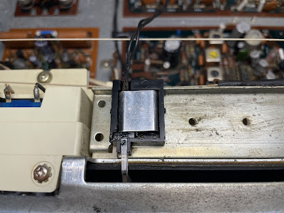
Dial pointer assembly - the plastic cover is removed
A new dial lamp is installed
The original dial and meter lamps in this unit were replaced with new warm white LED lamps (8V, wedge base). Again, replacing these lamps in this model is very easy in comparison to model 2230 (non B).
DC offset and Bias Adjustments
Be aware, that the service manual has an error for bias adjustment. The correct procedure is described below.
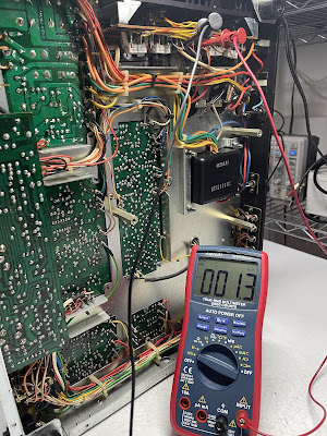
The Bias on the left channel is measured across two emitter resistors R759 and R761. So, the voltmeter should be connected between J714 (+) and J716 (-). On the right channel, the bias is measured across two emitter resistors R760 and R762. So, the voltmeter should be connected between J715 (+) and J717 (-). The Bias should be adjusted to ~20mV on each channel with the trimming resistors R733 and R734.
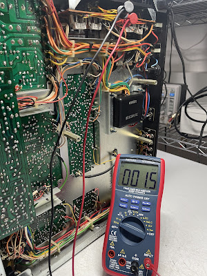
The DC offset on the left channel is measured between J723 and J722 (ground). On the right channel, it is measured between J724 and J722 (ground). The DC offset should be adjusted as close to zero volts as possible with the trimming resistors R711 and R712.
Bias on the left and right channels after restoration
DC offset on the left and right channels after restoration
Output Power Test
The final output power test was performed at the end of my restoration. The amplifier was loaded with a low inductance 8Ω/100W dummy resistor for each channel. The oscilloscope was connected across the speaker terminals and a sine-wave signal of 1kHz was applied to the AUX jacks. The output sine-wave signal was perfectly symmetrical on both channels with no clipping up to 16.20 VRMS (left channel) and 16.41 VRMS (right channel). It corresponds to the output power of 32.8W on the left channel and 33.7W on the right channel.
Output power test
As usual, all the knobs and the face plate were gently cleaned in warm water with dish soap. All controls have been cleaned with DeoxIT 5% contact cleaner and lubricated with DeoxIT FaderLube 5% spray.
The final result can be seen in the photos below. The receiver looks awesome again, the sound is clear and warm. Classic Marantz sound from the 70's! Please watch a short demo video at the end of this post. Thank you for reading.
Marantz 2230B - after restoration


_before%20servicing.jpg)
_after%20servicing.jpg)

_before%20servicing.jpg)
_after%20servicing.jpg)
_before%20servicing.jpg)
_after%20servicing.jpg)
_before%20servicing.jpg)
_after%20servicing.jpg)


_before%20servicing.jpg)
_after%20servicing.jpg)


Really nice & clean restore on this unit. I'd gladly trade my original unrestored 4230 for this model since I really don't have a need for Quad.
ReplyDeleteHello Mark, I'm sorry, but this receiver has already been sold.
DeleteAre you still doing 2230B restoration.
ReplyDeleteYes, sure.
DeletePozdrav, imam MARANTZ 2030B i radio je postao "gluv", a pojačalo je još i nekako radio sa malo šuštanja prilikom pojačavanja i oslabljenom snagom. Mehanilki je sve uredno i nema oštećenja.Spakovao sam to u neku kutiju i ostavio na policu. vredi li to popravljati?
ReplyDeleteYour Marantz 2230B is a classic vintage receiver from the 70s. I would definitely restore it.
Delete