Unit: AM/FM Stereo Receiver
Manufacturer: Pioneer
Model: SX-780
SN: YD3600495S
Another Pioneer SX-780 came in for a full restoration on my bench. The original owner purchased it new in 1978 and used it for many years enjoying the music. The unit is still in excellent cosmetic condition but had been sitting in storage for several decades. The owner recently pulled it from the storage, but the receiver quit working after running for a few hours.
Quick testing revealed that both original STK-0050 modules in this unit are toasted. The original Sanyo power modules are obsolete and no longer available on the market. And the "new" STK-0050 modules available on eBay are usually counterfeit from China. So, after discussion with the owner, we agreed to upgrade the toasted original STK modules with custom-made modules available from eBay seller "delta9electronics" located in Canada (no affiliation, but in my opinion his design and build quality are the best on the market).
A few years ago I serviced another SX-780 and published the restoration process in detail on my blog here: Pioneer SX-780 receiver restoration. In this post, I am going to focus only on the replacement of the original Sanyo power modules. Everything else in this unit was restored in the same manner as described in my previous post.
According to the Pioneer database, this particular unit was manufactured in April 1978.
STK-0050 Modules Troubleshooting
The original STK-0050 modules were unsoldered and tested with the digital multimeter in diode mode. Both modules were found to be toasted.
Test results on original STK-0050 modules (DMM in diode mode):
Left channel
pin 1 (-) and 3 (+): open circuit
pin 8 (-) and 0 (+): open circuit
Right channel
pin 1 (-) and 3 (+): open circuit
pin 8 (-) and 0 (+): 1.4V (Okay)
With the original STK-0050 modules removed from the PCB, I soldered two 1kΩ resistors to verify the front-end circuit. Each 1kΩ resistor was soldered between pins 0 and 8, and pins 1 and 3, respectively. The receiver was powered up and the DC voltage was measured at each pin. As can be seen from the test results below, the voltage measured at pins 1 and 0 was approximately equal but opposite in polarity. It indicates the correct behavior of the STK driver circuits.
Test results with the original STK-0050 modules removed and 1kΩ resistors soldered in place:
pin 1: left channel: -3.9V, right channel: -4.2V
pin 2: left channel: -39.8V, right channel: -39.9V
pin 3: left channel: 0V, right channel: 0V
pin 8: left channel: 0V, right channel: 0V
pin 9: left channel: +39.9V, right channel: +39.7V
pin 0: left channel: +4.0V, right channel: +4.2V
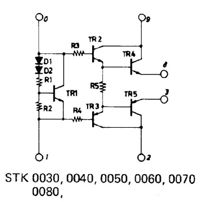
For reference, below are the equivalent circuit of the original STK-0050 module and custom-made replacement module from eBay seller "delta9electronics".
Original STK-0050 module - equivalent circuit
Custom-made replacement module - equivalent circuit
Installation of Replacement STK Modules
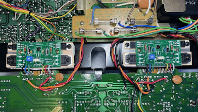
It is very easy to install the replacement modules in Pioneer SX-780. The new modules are larger than the original STK-0050 modules due to the wide aluminum heat sink. However, there is plenty of space there, and the mounting holes have the same spacing as in the original STK modules.
So, the original STK-0050 modules were unsoldered from the PCB, the heat sink was cleaned and degreased, and the replacement modules were installed. A thin film of silicone thermal compound (Wakefield-Vette, 120 series) was applied to the back side of the aluminum heat sink. The jumper wires were bent and soldered to the PCB.
Replacement STK module
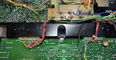
Original STK-0050 modules - unsoldered from the PCB
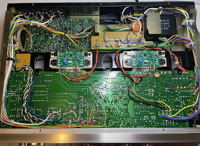
STK replacement modules are installed and soldered
DC offset and Bias Adjustments
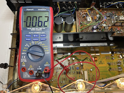
After verifying that there are no shorts, I powered up the SX-780 using the Dim Bulb Tester (DBT). The light bulb went bright for a second and then dimmed down almost completely. The protection relay clicked after a few seconds as well. I checked and adjusted the DC offset of the power amplifier as described in the service manual. No dummy load or input signal is required for this adjustment.
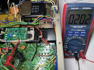
The replacement STK modules also allow adjusting the Bias in the SX-780 across the two 0.22Ω emitter resistors (pins 3 and 8). I adjusted the bias to ~20mV on each channel with a blue Bourns 500Ω trimming resistor.
DC offset on the left and right channel after restoration
Bias on the left and right channel after restoration
For reference, I also measured the voltage at each pin of replacement STK modules. These results confirm a normal operation of the output stage of AF power amplifier.
Test results on replacement STK modules:
pin 1: left channel: -1.2V, right channel: -1.2V
pin 2: left channel: -39.5V, right channel: -39.5V
pin 3: left channel: 0V, right channel: 0V
pin 8: left channel: 0V, right channel: 0V
pin 9: left channel: +39.5V, right channel: +39.5V
pin 0: left channel: +1.3V, right channel: +1.4V
Output Power Test
The final output power test was performed at the end of my restoration. The receiver was loaded with a low inductance 8Ω/100W dummy resistor for each channel. The oscilloscope was connected across the speaker terminals and a sine-wave signal of 1kHz was applied to the AUX jacks. The output sine-wave signal was perfectly symmetrical on both channels with no clipping up to 19.36 VRMS (left channel) and 19.18 VRMS (right channel). It corresponds to the output power of 46.9W on the left channel and 46.0W on the right channel.
Output power test
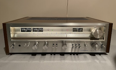
The final result can be seen in the photos below. The receiver looks brand new again and sounds awesome. I would highly recommend replacing the original toasted STK modules with custom-made ones instead of counterfeit modules from China. Please watch a short demo video at the end of this post. Thank you for reading.
Pioneer SX-780 - after restoration









what is 4R7 in your diagram
ReplyDeleteThese are 4.7 Ω resistors
Deletenice work mr oleg..!
ReplyDeleteThank you!
DeleteOleg, thank you for your detailed descriptions! They are extremely useful for aspiring new vintage stereo hobbyists! I have an SX-780 that has one channel completely out of whack - as soon as relay clicks, L channel's VU meter immediately jumps all the way to the right. I used your approach of disconnecting STKs, soldering resistors between STK contacts 1-3 and 8-0, and measuring voltages. R channel shows voltages very close to what you got but L channel is way off. Here is what I get: 1: +39V, 2:-42.1V, 3: +39V, 8: +39V, 9: +42.2, 0: +39.5. Clearly, something is not right with the L channel driver circuit. Do you have any recommendations on what to check?
ReplyDeleteI would check the following transistors in the left (bad) channel: Q11, Q13, and Q15. Most probably, these transistors are shorted.
Delete