Unit: AM/FM Stereo Receiver
Manufacturer: Pioneer
Model: SX-450
SN: XG3690374Y
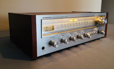
Today I'm showcasing a Pioneer SX-450 receiver that came in for restoration. The SX-450 is the smallest entry-level receiver from the great line of receivers that Pioneer ever produced. Even though it produces only 15 watts per channel into 8 ohms it still sounds as good as high-end models from the 50's series. It was built using the same standards as in big brothers and has an impressive sonic quality. According to the Pioneer database, this unit was manufactured in July 1977.
The servicing of Pioneer SX-450 is a pretty easy task except for a few hard-to-reach electronic components. It has only two PCBs and plenty of space inside. Below are some photos I took during my restoration process, complete with comments and recommendations.
RF Assembly Board
The microphone amplifier circuit has two tantalum electrolytic capacitors C231 and C235 installed in the signal path and one aluminum e-cap C232. All three capacitors are hard to reach since they are located between the small metal mounting plate and rotary switch. The mounting plate should be removed to reach those capacitors. It is easy to do if the faceplate and large black mounting plate have already been removed. Otherwise, I don't think it is possible to replace those capacitors. The working space is really very limited here. I replaced the C231 with film polyester WIMA MKS2 cap and C235 with film polyester Kemet cap. The electrolytic capacitor C232 was replaced with a low impedance and high-reliability Nichicon UPW cap.
Microphone amplifier circuit - before
The phono amplifier circuit has nine electrolytic capacitors: C203/C204, C217/C218, C207/C208, C209/C210, and C237. Four of them C203/C204 and C217/C218 are tantalum capacitors installed in the signal path. I replaced C203/C204 with low leakage Nichicon UKL caps, and C217/C218 with high-quality film polyester WIMA MKS2 caps, respectively.
There is confusion with capacitors C209 and C210. The schematic shows both e-caps as 100uF/16V despite the original capacitors installed on the board having rated capacitance 220uF/6.3V. At the same time, the parts list dictates these two positions as 100uF/10V. So, I replaced e-caps C209 and C210 with low impedance Nichicon UPW caps, 220uF/10V. Two tantalum capacitors C203 and C204 were replaced with low leakage Nichicon UKL caps. The other two tantalum capacitors C217 and C218 were replaced with film polyester WIMA MKS2 caps. And the remaining three electrolytic capacitors were replaced with low impedance Nichicon UPW caps.
Two PNP transistors Q201 and Q202 installed in the phono amplifier circuit are 2SA725. These transistors are known to become very noisy over time. I replaced them with modern low noise Fairchild KSA992. The new transistors were carefully matched by current gain and base-emitter voltage within 1%. Watch the pinout on replacement transistors. The original transistor is BCE and the new one is ECB.
Phono amplifier circuit - before and after
The control section employs two tantalum electrolytic capacitors C223/C224 installed in the signal path, and five aluminum e-caps C225/C226, C229/C230, C236. Both tantalum capacitors were replaced with film polyester WIMA MKS2 caps. The remaining e-caps were replaced with low impedance Nichicon UPW caps.
AF Assembly Board
The AF assembly board contains the power supply and tone control/power amplifier circuits.
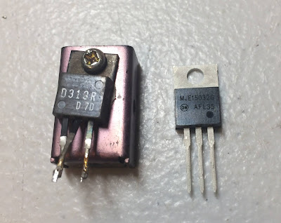
The power supply circuit provides +13.7V DC for the Tuner (pin #6) and +36.5V DC for the Tone control amplifier (pin #8). It also provides balanced power to the power amplifier from the bridge rectifier and two filter capacitors C309/C310. This circuit has six electrolytic capacitors C303 thru C307 and C311. I replaced them with low impedance Nichicon UPW caps. The regulating transistor Q302 mounted on a standalone heat sink was replaced with a Fairchild MJE transistor due to better thermal characteristics in comparison to the original transistor 2SD313R. A fresh thermal compound was applied between the new transistor and a heat sink.
Original regulating transistor Q302 - the old thermal grease is almost completely dried out
Original and new regulating transistor Q302
AF assembly board - before and after
The tone control/power amplifier circuit has six tantalum e-caps C109/C110, C201/C202, C219/C220 installed in the signal path, and six aluminum e-caps C207/C208, C211/C212, C221, C222. All tantalum capacitors were replaced with film polyester WIMA MKS2 caps. And all aluminum e-caps were replaced with low impedance Nichicon UPW/UPM caps.
The differential pair amplifier Q201/Q203 (left channel) and Q202/Q204 (right channel) consists of two notorious transistors 2SA725. Those transistors become very noisy over time and I replaced them with modern low-noise Fairchild KSA992. Keep in mind that transistor matching is very important in a differential pair amplifier for normal operating. I carefully matched each pair of KSA992 transistors by current gain and base-emitter voltage before installation. Below are test results on four original transistors removed from the board along with test results on four new closely matched transistors. As one can see the pair of original transistors in the right channel is poorly matched by current gain.
Test results on four original transistors 2SA725:
Left channel: Q201 (gain - 375, Vbe - 0.779V), Q203 (gain - 380, Vbe - 0.777V)
Right channel: Q202 (gain - 389, Vbe - 0.774V), Q204 (gain - 266, Vbe - 0.778V)
Test results on four new closely matched transistors KSA992:
Left channel: Q201 (gain - 405, Vbe - 0.759V), Q203 (gain - 406, Vbe - 0.758V)
Right channel: Q202 (gain - 405, Vbe - 0.760V), Q204 (gain - 407, Vbe - 0.759V)
Four power transistors Q211 thru Q214 were unsoldered from the heat sink and tested with Atlas DCA55 semiconductor analyzer. All of them have a current gain below the factory spec listed in the datasheet. The min current gain for the power transistor 2SD313R is 40. However, three out of four transistors have a gain of ~35, and the 4th transistor has a very low gain at 12. I replaced all of them with new Fairchild KSC2073 transistors. New Mica thermal pads and fresh thermal compound were applied between each power transistor and the heat sink.
Power transistor Q212 has a very low current gain
Test results on four original power transistors 2SD313R:
Left channel: Q211 (gain - 35, Vbe - 0.628V), Q213 (gain - 35, Vbe - 0.606V)
Right channel: Q212 (gain - 12, Vbe - 0.595V), Q214 (gain - 33, Vbe - 0.617V)
Test results on four new closely matched power transistors KSC2073:
Left channel: Q211 (gain - 65, Vbe - 0.702V), Q213 (gain - 65, Vbe - 0.701V)
Right channel: Q212 (gain - 65, Vbe - 0.702V), Q214 (gain - 65, Vbe - 0.703V)
Power transistors - original 2SD313R
Power transistors - new Fairchild KSC2073
Pilot and Stereo Indicator Lamps
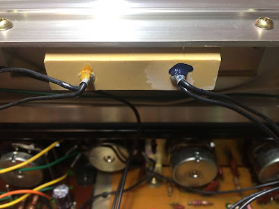
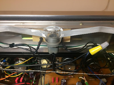
Both pilot and stereo indicator bulbs burned out in this unit. I replaced them with warm white LED lamps and secured them with super glue. The new LED lamps will virtually last forever. All dial bulbs were replaced with new incandescent bulbs.
The original pilot and stereo indicator bulbs
Replaced with warm white LED lamps
Bias Adjustment
The Pioneer SX-450 has no trimmers to adjust the Bias. Instead, it has two jumpers which should be cut if the voltage across the emitter resistor is less than 15mV. To check the bias I loaded this receiver with two low inductance 8Ω/100W dummy resistors across the speaker terminals. And then connected my DC voltmeter between terminal #19 and #20 for the left channel, and between terminal #17 and #18 for the right channel. The measured voltage was ~31.1mV on the left channel, and ~34.0mV on the right channel. This voltage is above 15mV, and hence no jumpers should be cut.
Bias on the left and right channel after restoration
As usual, all the knobs and the front panel were gently cleaned in warm water with dish soap. All knobs were also slightly polished by Mothers Mag & Aluminum polish to remove some small spots of aluminum oxidation.
The final result can be seen in the photos below. The receiver is fully restored and ready to play music for another 20-30 years. Please watch a short demo video at the end of this post. Thank you for reading.
Pioneer SX-450 - before restoration
Pioneer SX-450 - after restoration


Hi, thanks for posting this - I found a working SX-450 at the thrift a few years ago (with bulbs still functioning!) and only recently set it up on our living room mantelpiece with a couple of JM Lab Chorus 706 speakers (quite sensitive). The results are wonderful for a bookshelf system.
ReplyDelete