Unit: AM/FM Stereo Receiver
Manufacturer: Pioneer
Model: SX-434
SN: WB3943648Y
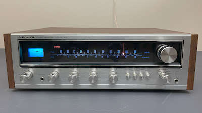
Today I'm showcasing a Pioneer SX-434 receiver that came in for restoration. The SX-434 is Pioneer's budget-priced stereo receiver. It produces only 15 watts per channel into 8 ohms but has an excellent build quality and a very sensitive FM tuner with low noise FET and 3-gang frequency linear variable capacitor. The total harmonic distortion is less than 0.8%. The damping factor at 8 ohms is 25. The SX-434 was manufactured from 1974 to 1976. It is a very nice-looking receiver with a warm and rich sound. The retail price in 1975 was $239.95 (Ref. Stereo Review, Stereo Directory 1975, page 45).
According to the Pioneer database, this particular unit was manufactured in February 1976.
Power Supply Board (AWR-062)
The power supply board has 6 electrolytic capacitors C7, C8, C9, C10, C11, and C12.
All of them were replaced with low-impedance and high-reliability Nichicon UPW/UPM caps.
The original e-caps were tested with an Atlas ESR70 capacitance meter; the results are below.
Test results on original capacitors removed from the power supply board:
C7: rated capacitance – 330uF, measured – 394uF, ESR – 0.52Ω, deviation: +19%
C8: rated capacitance – 100uF, measured – 116uF, ESR – 0.31Ω, deviation: +16%
C9: rated capacitance – 100uF, measured – 105uF, ESR – 0.42Ω, deviation: +5%
C10: rated capacitance – 100uF, measured – 127uF, ESR – 1.12Ω, deviation: +27%
C11: rated capacitance – 100uF, measured – 118uF, ESR – 0.55Ω, deviation: +18%
C12: rated capacitance – 220uF, measured – 218uF, ESR – 0.32Ω, deviation: -1%
This board is easy to service but pay attention to the old nylon snap lock supports. Over time they become brittle and can be easily broken if too much force is used to separate the board from the chassis.
Power supply board - before and after
AF Amplifier Board (AWK-034)
The cleaning and lubricating of all pots and switches are routine work on any vintage gear. Some models have very easy access to pots/switches by design, and it usually takes just 10-15 minutes to thoroughly clean all of them. However, in other models, this routine work could be a real challenge. The Pioneer SX-434 is one of them. Cleaning the pots and switches in this model is impossible without disassembling the AF amplifier board from the chassis. In addition, it is a little bit tricky to take it out due to the large heat sink with an unusual shape. The function switch was loosened and the headphone jack was removed from the chassis to facilitate this process. Moreover, the power supply board was also removed from the chassis since one screw holding the heat sink is located just under the power supply board! Anyway, after the board was successfully disassembled from the chassis I thoroughly cleaned all pots and switches with DeoxIT 5% contact cleaner and lubricated them with DeoxIT FaderLube 5% spray.
The AF amplifier board has 10 notorious sky-blue Sanyo e-caps (C1, C2, C17, C18, C23, C24, C35, C36, C37, C38) installed in the signal path, two low-leakage e-caps (C11, C12), and 10 ordinary aluminum electrolytic capacitors (C41, C42, C43, C44, C51, C52, C55, C56, C57, C58).
All Sanyo coupling capacitors were replaced with high-quality film polyester WIMA caps. The original low-leakage e-caps were replaced with modern low-leakage Nichicon UKL caps. Two original aluminum e-caps C56 and C58 were replaced with Nichicon UFG caps. The remaining aluminum capacitors were replaced with low-impedance Nichicon UPW caps.
Test results on original capacitors removed from the AF amplifier board:
C1: rated capacitance – 1uF, measured – 1.0uF, ESR – 4.4Ω, deviation: 0%
C2: rated capacitance – 1uF, measured – 1.2uF, ESR – 3.6Ω, deviation: +20%
C11: rated capacitance – 3.3uF, measured – 4.2uF, ESR – 8.8Ω, deviation: +27%
C12: rated capacitance – 3.3uF, measured – 3.9uF, ESR – 10.6Ω, deviation: +18%
C17: rated capacitance – 1uF, measured – 1.3uF, ESR – 5.8Ω, deviation: +30%
C18: rated capacitance – 1uF, measured – 1.2uF, ESR – 4.8Ω, deviation: +20%
C23: rated capacitance – 0.33uF, measured – 0.38uF, ESR – N/A, deviation: +15%
C24: rated capacitance – 0.33uF, measured – 0.37uF, ESR – N/A, deviation: +12%
C35: rated capacitance – 0.47uF, measured – 0.52uF, ESR – N/A, deviation: +11%
C36: rated capacitance – 0.47uF, measured – 0.52uF, ESR – N/A, deviation: +11%
C37: rated capacitance – 0.47uF, measured – 0.55uF, ESR – N/A, deviation: +17%
C38: rated capacitance – 0.47uF, measured – 0.54uF, ESR – N/A, deviation: +15%
C41: rated capacitance – 220uF, measured – 242uF, ESR – 0.36Ω, deviation: +10%
C42: rated capacitance – 220uF, measured – 240uF, ESR – 0.42Ω, deviation: +9%
C43: rated capacitance – 47uF, measured – 57uF, ESR – 0.67Ω, deviation: +21%
C44: rated capacitance – 47uF, measured – 57uF, ESR – 0.77Ω, deviation: +21%
C51: rated capacitance – 220uF, measured – 235uF, ESR – 0.32Ω, deviation: +7%
C52: rated capacitance – 220uF, measured – 233uF, ESR – 0.26Ω, deviation: +6%
C55: rated capacitance – 47uF, measured – 55uF, ESR – 0.83Ω, deviation: +17%
C56: rated capacitance – 330uF, measured – 355uF, ESR – 1.31Ω, deviation: +8%
C57: rated capacitance – 220uF, measured – 239uF, ESR – 0.26Ω, deviation: +9%
C58: rated capacitance – 330uF, measured – 357uF, ESR – 0.22Ω, deviation: +8%
This board has a bunch of small signal transistors that are prone to failure.
Original Hitachi 2SC1344 NPN transistors installed in positions Q1, Q2, Q3, Q4, Q5, and Q6 often create static noise in the circuit. They also have a relatively high failure rate due to early degradation. I replaced them with new Fairchild KSC1845 transistors. Watch the pinout on replacement transistors. The original transistor is BCE and the new one is ECB.
The first stage of the AF amplifier circuit is a differential amplifier consisting of two transistors with a common emitter: Q10 & Q12 (left channel) and Q11 & Q13 (right channel). The original PNP transistor installed in these positions is 2SA725. This transistor is infamous for creating a shot noise in the circuit. I replaced each pair of original 2SA725 transistors with a new close-matched pair of modern low-noise Fairchild KSA992 transistors. Each pair of new KSA992 transistors was carefully matched (within ~1%) by current gain and base-emitter voltage. Watch the pinout on replacement transistors. The original transistor is BCE and the new one is ECB.
Test results on original 2SA725 transistors
Q10 (left channel): hfe - 497, Vbe - 0.770V
Q12 (left channel): hfe - 457, Vbe - 0.772V
Q11 (right channel): hfe - 510, Vbe - 0.761V
Q13 (right channel): hfe - 547, Vbe - 0.763V
Test results on new KSA992 transistors
Q10 (left channel): hfe - 424, Vbe - 0.756V
Q12 (left channel): hfe - 421, Vbe - 0.758V
Q11 (right channel): hfe - 419, Vbe - 0.755V
Q13 (right channel): hfe - 418, Vbe - 0.757V
Original Panasonic 2SC1318 NPN transistors installed in positions Q14, Q15, Q16, and Q17 often suffer from thermal stress. I replaced them with new Fairchild KSC2383 transistors.
A complementary pair to the 2SC1318 transistor is a Panasonic 2SA720. This transistor is installed in positions Q18 and Q19. I replaced the original 2SA720 transistors with new Fairchild KSA1013s.
AF amplifier board - disassembled from the chassis
AF amplifier board - before and after
Tuner Board (AWE-052)
The tuner board has 6 notorious sky-blue Sanyo capacitors (C36, C48, C49, C50, C59, C60) and 10 aluminum electrolytic capacitors (C18, C21, C25, C26, C28, C32, C33, C39, C44, C61).
The original Sanyo e-cap C36 was replaced with a film polyester Kemet capacitor. The other Sanyo capacitors and two ordinary aluminum e-caps C21 and C25 were replaced with film polyester WIMA caps. The remaining aluminum e-caps were replaced with low-impedance Nichicon UPW caps.
Test results on original capacitors removed from the tuner board:
C18: rated capacitance – 4.7uF, measured – 5.2uF, ESR – 2.4Ω, deviation: +11%
C21: rated capacitance – 0.47uF, measured – 0.47uF, ESR – N/A, deviation: 0%
C25: rated capacitance – 1uF, measured – 1.3uF, ESR – 2.6Ω, deviation: +30%
C26: rated capacitance – 10uF, measured – 12uF, ESR – 1.64Ω, deviation: +20%
C28: rated capacitance – 100uF, measured – 117uF, ESR – 0.52Ω, deviation: +17%
C32: rated capacitance – 4.7uF, measured – 5.2uF, ESR – 2.9Ω, deviation: +11%
C33: rated capacitance – 47uF, measured – 56uF, ESR – 1.31Ω, deviation: +19%
C36: rated capacitance – 0.1uF, measured – 0.1uF, ESR – N/A, deviation: 0%
C39: rated capacitance – 10uF, measured – 12uF, ESR – 1.59Ω, deviation: +20%
C44: rated capacitance – 10uF, measured – 12uF, ESR – 2.2Ω, deviation: +20%
C48: rated capacitance – 0.33uF, measured – 0.35uF, ESR – N/A, deviation: +6%
C49: rated capacitance – 1uF, measured – 1.3uF, ESR – 4.6Ω, deviation: +30%
C50: rated capacitance – 0.47uF, measured – 0.42uF, ESR – N/A, deviation: -11%
C59: rated capacitance – 0.33uF, measured – 0.34uF, ESR – N/A, deviation: +3%
C60: rated capacitance – 0.33uF, measured – 0.32uF, ESR – N/A, deviation: -3%
C61: rated capacitance – 220uF, measured – 239uF, ESR – 0.36Ω, deviation: +9%
The original PNP transistors installed in positions Q8 and Q9 are notorious 2SA725 transistors. I replaced them with modern low-noise Fairchild KSA992. Watch the pinout on replacement transistors. The original transistor is BCE and the new one is ECB.
Tuner board - before and after
Dial, Meter, and Dial Pointer Lamps
Replacing the dial and tuning meter lamps in SX-434 is a very simple task. To release the lamp housing that holds the dial and meter lights, simply unscrew the two small screws at the top of the lamp housing. And then carefully remove it from the chassis. I replaced the original dial lamps with modern warm white LED lamps to maintain the original look and reduce heat. The original incandescent light bulb installed behind the tuning meter usually overheats the plastic of the meter and discolors it. As a result, the plastic often turns yellowish. I replaced the original tuning meter bulb with a cool blue LED lamp to solve this problem and better match the tuning meter with the rest of the dial.
New LED-type dial and meter lamps installed
The stereo indicator bulb burned out in this unit and I replaced it with a new incandescent bulb. This is a very delicate work since the original rubber holder dries out over time and eventually becomes very brittle. I used an X-ACTO #2 Knife to remove the original bulb from the holder carefully trimming around the bulb. The diameter of the new incandescent bulb is smaller than the original one and to compensate for the difference I put on a heat shrink on a new bulb. After that, the new incandescent bulb was inserted into the holder and secured with super glue.
A new stereo indicator lamp installed
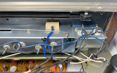
The dial pointer bulb burned out in this unit as well and it was probably the most challenging work for me in this model. It is not so easy to replace a burned-out dial pointer bulb in Pioneer SX-434. Ideally, the dial pointer holder should be removed from the dial panel before bulb replacement. But in that case, the holder should be disassembled from the dial string. I didn't want to break the factory sealing and decided to replace the burned bulb without disassembling the dial pointer holder from the dial string. Well, I wouldn't say it is an easy task but it is doable with extra care and with the right tools. I used an X-ACTO #2 Knife again and small pliers to release a plastic dial holder from the metal part. Be extra cautious during this step if you need to replace a dial pointer bulb in this model. It is very easy to break a plastic needle. I was patient and lucky. The plastic needle was not broken and I successfully replaced the old bulb with a new one!
Original dial pointer lamp - removed from the plastic holder
DC offset and Bias Adjustments
The service manual describes step-by-step the power amplifier alignment but these instructions could be confusing for someone who is not familiar with this model. The problem is that this receiver has no trimmers to adjust the DC offset or Bias. Instead, it has three jumpers per channel which should be cut to make a correct alignment.
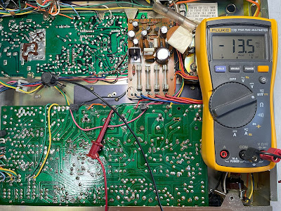
The first step is to check the DC offset. To do this I connected my DC voltmeter between terminal #27 and the ground. The measured voltage was ~17mV which is perfectly normal. Then, I connected the DC voltmeter between terminal #24 and the ground. The measured voltage was ~13mV which is again in an acceptable range. Ideally, the measured voltage should be as close as possible to zero volts. But in real life, any DC offset less than 30mV would be just fine. So, I didn't cut any jumpers and left them alone. However, if the measured voltage is above 40-50mV then the correct jumper lead should be cut to get the DC offset close to zero volts. Jumper C should be cut if the DC voltmeter reads a positive voltage between terminal #27 and the ground (i.e. > +50mV). Jumper E should be cut if the DC voltmeter reads a negative voltage between terminal #27 and the ground (i.e. < -50mV). Jumpers D or F should be cut if a positive or negative voltage is measured between terminal #24 and the ground.
DC offset on the left and right channels after restoration
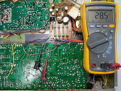
The second step is to check Bias. According to the service manual, the bias should be above 5mV otherwise the jumper lead should be cut. I connected my DC voltmeter between terminals TP1 and 27. The measured voltage was ~23mV which is above the minimal voltage stated in the service manual. The measured voltage between terminal number TP2 and 24 was ~28mV which is again in an acceptable range. So, no jumpers were cut here as well. If the measured voltage between terminal number TP1 (TP2) and 27 (24) is less than 5mV then the jumper A (B) should be cut.
Bias on the left and right channels after restoration
Output Power Test
The final output power test was performed at the end of my restoration. The receiver was loaded with a low inductance 8Ω/100W dummy resistor for each channel. The oscilloscope was connected across the speaker terminals and a sine-wave signal of 1kHz was applied to the AUX jacks. The output sine-wave signal was perfectly symmetrical on both channels with no clipping up to 11.45 VRMS (left channel) and 11.64 VRMS (right channel). It corresponds to the output power of 16.4W on the left channel and 16.9W on the right channel.
Output power test
As usual, all the knobs and the faceplate were gently cleaned in warm water with dish soap. All knobs were also slightly polished by Mothers Mag & Aluminum polish to remove some small spots of aluminum oxidation.
The final result can be seen in the photos below. As I mentioned earlier this receiver has a very warm and rich sound. And it looks very cool too! Please watch a short demo video at the end of this post. Thank you for reading.
Pioneer SX-434 - after restoration


_disassembled%20from%20the%20chassis.jpg)
_before%20servicing.jpg)
_after%20servicing.jpg)
_before%20servicing.jpg)
_after%20servicing.jpg)


Oleg seems up with this masterfully restored 434. I had a good sense about his passion from reading through this blog and once I saw the receiver, I knew he was the real the deal. The quality and detail Oleg put into this unit shows and I feel very lucky to have come across him.
ReplyDeleteIf you’re wondering where to find someone who really understands vintage hifi receivers, look no further. I would trust anything this man’s hand graces.
Thanks again!
Cheers,
Paul
Thank you Paul. I am glad that you are happy with this receiver.
DeleteI have exactly this Pioneer unit and the tuning needle that shows the frequency has broken would you be able to help me finding another one possibly?
ReplyDeleteYou might want to contact Oak Tree Vintage. They have a lot of spare parts from different models. This is a link to Pioneer spare parts: http://www.oaktreevintage.com/Pioneer_Stereo_Parts_Salvage_Units.htm
DeleteOccasionally the dial pointer for this model is also available on Ebay.
Thanks for some great advice here. I am replacing the transistors Q20, Q21, Q22 and Q23 in the power amp. These are the ones fixed to the large heat sink, and you do not mentioned replacing these. Now they have produce a continuous loud crack and popping sound when I reconnect it. I wonder if I've not used the correct equivalents. For D313D I used 2n5298 and for 507D I used TIP42L. The pinouts on both are BCE from L to R. One comment in Badcaps site for this suggests MJE15033G and MJE15032G. Any further advice on this, please?
ReplyDeleteHello Ric, the original 2SD313 and 2SB507 transistors are complementary pair. These are designed for the output stage of low power AF amplifiers. I would recommend to use the following modern substitutes: KSC2073TU for 2SD313 (Q20/Q21) and KSA940TU for 2SB507 (Q22/Q23). The modern KSC2073 transistor is complement to KSA940. I serviced four SX-434's in the past two years and one of them had toasted output transistors. I replaced the toasted transistors with KSC2073 and KSA940, and had a great result.
DeleteGreat, thanks Oleg! Will follow this and report back. Best rgds, Ric
DeleteNice job there Oleg. I have this receiver and the phono seems a little muddy. I think it can sounds better. Any recommendations?
ReplyDeleteThanks
Just purchased 2 of these units for $20.00 a piece. Both come on and work. A couple of bulbs are out, but plans are to restore each of them to their glory, Glad I found this posting. I will be following it.
ReplyDelete