Home

Thursday, October 28, 2021

Pioneer SA-7500 II Stereo Integrated Amplifier Restoration

Unit: Stereo Integrated Amplifier
Manufacturer: Pioneer
Model: SA-7500 II
SN: XH36111130 

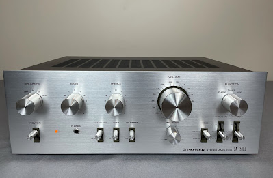
Today I'm showcasing a Pioneer SA-7500 II stereo integrated amplifier that came in for restoration. The SA-7500 II was manufactured from 1975 to 1978. It produces 40 watts per channel into 8 ohms with no more than 0.3% total harmonic distortion. The rear panel of SA-7500 II has input jacks for two turntables, two tape decks, a tuner, and an auxiliary source.

This particular unit is in perfect cosmetic condition and has no issues with electronics. I completed just routine servicing, i.e. cleaning and lubricating all the controls, replacing all electrolytic capacitors, bias adjustment checking, and final output power test. According to the Pioneer database, this particular unit was manufactured in August 1977.

Pioneer SA-7500 II_After Restoration

Control Amplifier Board (AWG-047)

The control amplifier board AWG-047 is mounted to the sub-panel. In general, this board can be serviced without removing it from the chassis. However, two variable resistors (Bass and Treble) are assembled on the board and it is much easier to clean them when the board is being removed. So, I cleaned and lubricated both variable resistors with DeoxIT FaderLube 5% spray. The Volume variable resistor is assembled on its own small board and also mounted to the sub-panel. I cleaned it with DeoxIT FaderLube 5% spray as well. Finally, all the switches were cleaned with DeoxIT 5% contact cleaner and then lubricated with DeoxIT FaderLube 5% spray.

The original low leakage e-caps C5, C6, C9, and C10 installed in the signal path were replaced with modern low leakage Nichicon UKL capacitors. The remaining aluminum e-caps C19 and C20 were replaced with low impedance and high-reliability Nichicon UPW caps. All original e-caps removed from this board were tested with Atlas ESR70 capacitance meter and results are below. All of them except e-cap C5 are outside the factory capacitance tolerance +/- 20%.

Test results on original capacitors removed from the control amplifier board:

C5: rated capacitance – 47uF, measured – 54uF, ESR – 1.49Ω, deviation: +15%
C6: rated capacitance – 47uF, measured – 57uF, ESR – 1.23Ω, deviation: +21%
C9: rated capacitance – 3.3uF, measured – 4.2uF, ESR – 1.14Ω, deviation: +27%
C10: rated capacitance – 3.3uF, measured – 4.3uF, ESR – 1.21Ω, deviation: +30%
C19: rated capacitance – 47uF, measured – 59uF, ESR – 0.05Ω, deviation: +26%
C20: rated capacitance – 47uF, measured – 57uF, ESR – 0.16Ω, deviation: +21%

Control amplifier board (AWG-047) - before and after

Pioneer SA-7500 II_Control Amplifier_before

Pioneer SA-7500 II_Control Amplifier_after

AF Amplifier Board (AWK-079)

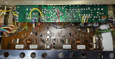
The power supply, protection, phono equalizer, and power amplifier circuits are assembled on one board (AWK-079).

The power supply and protection circuit has 10 aluminum e-caps: C45 thru C48, C54 thru C56, and C58 thru C60. All of them were replaced with low impedance Nichicon UPW/UPM caps.

Test results on original capacitors removed from the power supply and protection circuit:

C45: rated capacitance – 330uF, measured – 372uF, ESR – 0.08Ω, deviation: +13%
C46: rated capacitance – 330uF, measured – 373uF, ESR – 0.08Ω, deviation: +13%
C47: rated capacitance – 100uF, measured – 117uF, ESR – 0.12Ω, deviation: +17%
C48: rated capacitance – 2.2uF, measured – 2.1uF, ESR – 4.9Ω, deviation: -5%
C54: rated capacitance – 330uF, measured – 356uF, ESR – 0.01Ω, deviation: +8%
C55: rated capacitance – 330uF, measured – 344uF, ESR – 0.01Ω, deviation: +4%
C56: rated capacitance – 220uF, measured – 227uF, ESR – 0.02Ω, deviation: +3%
C58: rated capacitance – 47uF, measured – 52uF, ESR – 0.24Ω, deviation: +11%
C59: rated capacitance – 100uF, measured – 107uF, ESR – 0.08Ω, deviation: +7%
C60: rated capacitance – 220uF, measured – 263uF, ESR – 0.01Ω, deviation: +20%

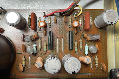
The phono equalizer circuit has four low leakage e-caps installed in the input (C1, C2) and output (C23, C24) signal path, two filtering aluminum e-caps (C61, C62), and two DC blocking aluminum e-caps (C9, C10) in the RIAA feedback loop. The e-caps installed in the input signal path were replaced with high-quality film polyester WIMA MKS2 caps. The e-caps installed in the output signal path were replaced with modern low leakage Nichicon UKL capacitors. Pay attention to the polarity of e-caps C23 and C24 installed in the output signal path. The polarity on the silkscreen is backward! The remaining four aluminum e-caps were replaced with low impedance Nichicon UPW caps.

The polarity of e-caps C23 & C24 is backward on the silkscreen

Pioneer SA-7500 II_Phono Equalizer_C23 & C24_Polarity is backwards

Test results on original capacitors removed from the phono equalizer circuit:

C1: rated capacitance – 1uF, measured – 1.1uF, ESR – 4.4Ω, deviation: +10%
C2: rated capacitance – 1uF, measured – 1.1uF, ESR – 5.1Ω, deviation: +10%
C9: rated capacitance – 220uF, measured – 264uF, ESR – 0.04Ω, deviation: +20%
C10: rated capacitance – 220uF, measured – 270uF, ESR – 0.05Ω, deviation: +23%
C23: rated capacitance – 2.2uF, measured – 2.8uF, ESR – 2.1Ω, deviation: +27%
C24: rated capacitance – 2.2uF, measured – 2.7uF, ESR – 2.4Ω, deviation: +23%
C61: rated capacitance – 220uF, measured – 265uF, ESR – 0.04Ω, deviation: +21%
C62: rated capacitance – 220uF, measured – 254uF, ESR – 0.06Ω, deviation: +16%

Phono equalizer circuit - before and after
Pioneer SA-7500 II_Phono Equalizer_before

Pioneer SA-7500 II_Phono Equalizer_after

The power amplifier circuit has two low leakage e-caps C31, C32 installed in the signal path, and two aluminum e-caps C35, C36 installed in the negative feedback loop. The e-caps installed in the input path were replaced with modern low leakage Nichicon UKL capacitors. And the remaining two aluminum e-caps were replaced with low impedance Nichicon UPW caps.

Test results on original capacitors removed from the power amplifier circuit:

C31: rated capacitance – 2.2uF, measured – 2.8uF, ESR – 2.1Ω, deviation: +27%
C32: rated capacitance – 2.2uF, measured – 2.7uF, ESR – 2.1Ω, deviation: +23%
C35: rated capacitance – 47uF, measured – 56uF, ESR – 0.74Ω, deviation: +19%
C36: rated capacitance – 47uF, measured – 55uF, ESR – 0.79Ω, deviation: +17%

AF amplifier board (AWK-079) - before and after

Pioneer SA-7500 II_AF Amplifier Board (AWK-079)_before servicing

Pioneer SA-7500 II_AF Amplifier Board (AWK-079)_after servicing

Bias Adjustments

The bias in Pioneer SA-7500 II is measured across two emitter resistors R57/R59 on the left channel (terminals TP1 and TP2) and across R58/R60 on the right channel (terminals TP3 and TP4). According to the service manual, the DC voltmeter reading tolerance is from 10mV to 70mV. This model has no trimmers for bias adjustments. Instead, it has one jumper per channel which should be cut if the voltage is less than 10mV. I measured the bias in each channel and the DC voltmeter reading was close to the middle of factory tolerance. So, no jumper leads were cut.

Bias on the left and right channel after restoration

Pioneer SA-7500 II_Bias_left channel

Pioneer SA-7500 II_Bias_right channel

Output Power Test

The final output power test was performed at the end of my restoration. The amplifier was loaded with a low inductance 8Ω/100W dummy resistor for each channel. The oscilloscope was connected across the speaker terminals and a sine-wave signal of 1kHz was applied to the AUX jacks. The output sine-wave signal was perfectly symmetrical on both channels with no clipping up to 18.96 VRMS (left channel) and 19.23 VRMS (right channel). It corresponds to the output power of 44.9W on the left channel and 46.2W on the right channel.

Output power test

Pioneer SA-7500 II_Output Power Test

As usual, all the knobs and the front panel were gently cleaned in warm water with dish soap. All knobs were also slightly polished by Mothers Mag & Aluminum polish to remove some small spots of aluminum oxidation.

The final result can be seen in the photos below. This amplifier looks really very cool: clean and shiny. The sound is rich and very detailed. Please watch a short demo video at the end of this post. Thank you for reading.

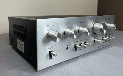
Pioneer SA-7500 II - after restoration

Pioneer SA-7500 II_After Restoration

Pioneer SA-7500 II_After Restoration_02

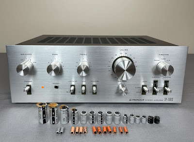
Pioneer SA-7500 II_After Restoration_with parts

Demo video after repair & restoration


Sunday, September 12, 2021

Pioneer SX-750 Receiver Restoration

Unit: AM/FM Stereo Receiver
Manufacturer: Pioneer
Model: SX-750
SN: YC3683249S

Today I'm showcasing a Pioneer SX-750 stereo receiver that came in for restoration. The SX-750 was and still is one of the most popular and well-respected receivers from the 70's. It was initially introduced in 1976 and made through 1978. The receiver produces 50 watts per channel into 8 ohms with no more than 0.1% total harmonic distortion. The unit is quite heavy and weighs about 30 pounds without a package. As Pioneer states in its 1976's brochure "for a practically-priced integrated receiver, Pioneer's SX-750 delivers an astonishing amount of state-of-the-art perfection. It is innovative, attractive, and value-packed". And it's hard to argue! According to the Pioneer database, this particular unit was manufactured in March 1978.

The restoration of the smaller brothers of SX-750 can be found on my blog here: Pioneer SX-450 receiver restoration and Pioneer SX-650 receiver restoration.

Pioneer SX-750_After servicing_01

This particular receiver came in for a restoration with a broken original Speaker Selector/Power switch. The owner took it up to a local repair shop to fix this issue but the technician just simply bypassed the original switch with a new one. The new switch was assembled on the left side panel. This is definitely not the best solution to the problem but this switch is a common issue on those Pioneer receivers. The switch can't be fixed by cleaning and there are no more new replacements available on the market. The best solution would be to disassemble the switch, clean up carbonized contacts with very fine sandpaper and then assemble it. I have tried to repair such a switch several times in the past but the reliability of the repaired switch is always in question. I usually prefer to replace it with a new switch if it is available. So, the owner decided to leave it alone and replace it probably later.

Bypassed Speaker Selector/Power switch - installed in the repair shop

Pioneer SX-750_Bypassed power switch_01

Pioneer SX-750_Bypassed power switch_02

Power Supply & Protection Assembly (AWR-099)

The power supply & protection circuits are assembled on one board (AWR-099). This board has 17 aluminum electrolytic capacitors: C1 thru C13, and C15 thru C18.
 
The original coupling capacitors C1 & C2 installed on this board are failure-prone sky blue Sanyo e-caps. As expected, the measured capacitance of these two e-caps is outside of factory capacitance tolerance. For more information about sky blue Sanyo e-caps refer to my previous post on Pioneer SX-828 restoration. I replaced them with high-quality film polyester Kemet capacitors.

The original aluminum e-caps C17 and C18 are rated at 330uF/50V. However, these two capacitors are running very close to their maximum rated voltage in the circuit. As a result, they are aging very fast and can completely fail at any time. I replaced them with 330uF/63V low impedance and high-reliability Nichicon UPM caps. It will substantially improve the reliability and extend a capacitor lifespan.

As can be seen from the test results below, at least five more original e-caps from this board are also outside of factory capacitance tolerance. I replaced all remaining aluminum e-caps with low impedance Nichicon UPW/UPM caps.

Test results on original capacitors removed from the power supply & protection board:

C1: rated capacitance – 0.22uF, measured – 0.29uF, ESR – N/A, deviation: +32%
C2: rated capacitance – 0.22uF, measured – 0.32uF, ESR – N/A, deviation: +46%
C3: rated capacitance – 330uF, measured – 362uF, ESR – 0.12Ω, deviation: +10%
C4: rated capacitance – 330uF, measured – 374uF, ESR – 0.11Ω, deviation: +13%
C5: rated capacitance – 3.3uF, measured – 4.2uF, ESR – 0.8Ω, deviation: +27%
C6: rated capacitance – 220uF, measured – 218uF, ESR – 0.08Ω, deviation: -1%
C7: rated capacitance – 220uF, measured – 151uF, ESR – 0.12Ω, deviation: -31%
C8: rated capacitance – 100uF, measured – 73uF, ESR – 0.12Ω, deviation: -27%
C9: rated capacitance – 100uF, measured – 95uF, ESR – 0.13Ω, deviation: -5%
C10: rated capacitance – 100uF, measured – 95uF, ESR – 0.14Ω, deviation: -5%
C11: rated capacitance – 4.7uF, measured – 6.1uF, ESR – 1.48Ω, deviation: +30%
C12: rated capacitance – 220uF, measured – 138uF, ESR – 0.14Ω, deviation: -37%
C13: rated capacitance – 100uF, measured – 95uF, ESR – 0.04Ω, deviation: -5%
C15: rated capacitance – 100uF, measured – 84uF, ESR – 0.16Ω, deviation: -16%
C16: rated capacitance – 100uF, measured – 90uF, ESR – 0.06Ω, deviation: -10%
C17: rated capacitance – 330uF, measured – 261uF, ESR – 0.01Ω, deviation: -21%
C18: rated capacitance – 330uF, measured – 185uF, ESR – 0.01Ω, deviation: -44%

The original PNP transistor 2SB507 installed on this board is running pretty hot under normal operating conditions (by circuit design) but has no heat sink. I mounted a low-profile heat sink on this transistor to improve heat dissipation. The heat sink is small enough and doesn't touch any nearby components. The manufacturer's part number is 577404B00000G (Aavit).

Low profile heat sink mounted on original PNP transistor Q12

Pioneer SX-750_Power Supply & Protection Assembly (AWR-099)_Heat sink mounted on transistor Q12

Power supply & protection assembly (AWR-099) - before and after

Pioneer SX-750_Power Supply & Protection Assembly (AWR-099)_before servicing

Pioneer SX-750_Power Supply & Protection Assembly (AWR-099)_after servicing

Filter & Muting Assembly (AWM-094)

The filter and muting circuits are assembled on one board (AWM-094). The access to the foil side of this board is blocked by a bunch of wires. I recommend removing the metal angle supporting this board to get better access. Otherwise, there is a high risk of touching some of these wires with a hot soldering iron. Don't forget to screw back a small ground plate with a wire coming from the power supply & protection board (pin #12) after the servicing is done. Also, re-flow the pad under the screw to improve ground contact.

This board has three solid tantalum capacitors C1, C2, C7, and two aluminum electrolytic capacitors C3 and C5. The capacitors C1 and C2 installed in the signal path after the low pass filter were replaced with modern low leakage Nichicon UKL capacitors. The capacitor C7 was replaced with a high-quality film polyester WIMA MKS2 cap. And the remaining two capacitors C3 and C5 were replaced with low impedance Nichicon UPW/UPM caps.

Test results on original capacitors removed from the filter and muting board:

C1: rated capacitance – 2.2uF, measured – 2.1uF, ESR – 4.1Ω, deviation: -5%
C2: rated capacitance – 2.2uF, measured – 2.2uF, ESR – 3.2Ω, deviation: 0%
C3: rated capacitance – 10uF, measured – 12uF, ESR – 0.56Ω, deviation: +20%
C5: rated capacitance – 100uF, measured – 87uF, ESR – 0.06Ω, deviation: -13%
C7: rated capacitance – 1uF, measured – 1uF, ESR – 1.12Ω, deviation: 0%

Filter & muting assembly (AWM-094) - before and after

Pioneer SX-750_Filter & Muting Assembly (AWM-094)_before servicing

Pioneer SX-750_Filter & Muting Assembly (AWM-094)_after servicing

Tuner, AF, & Control Assembly (AWE-073)

The tuner, phono equalizer, and microphone circuits are all assembled on the same board (AWE-073).

The phono equalizer circuit has four solid tantalum e-caps installed in the input (C82, C83) and output (C98, C99) signal path, two filtering aluminum e-caps (C84, C85), and two DC blocking aluminum e-caps (C88, C89) in the RIAA feedback loop. All original tantalum capacitors were replaced with low leakage Nichicon UKL caps. The remaining four aluminum e-caps were replaced with low impedance Nichicon UPW caps.

Test results on original capacitors removed from the phono equalizer circuit:

C82: rated capacitance – 2.2uF, measured – 2.3uF, ESR – 1.48Ω, deviation: +5%
C83: rated capacitance – 2.2uF, measured – 2.2uF, ESR – 1.85Ω, deviation: 0%
C84: rated capacitance – 220uF, measured – 278uF, ESR – 0.02Ω, deviation: +26%
C85: rated capacitance – 220uF, measured – 280uF, ESR – 0.02Ω, deviation: +27%
C88: rated capacitance – 100uF, measured – 112uF, ESR – 0.31Ω, deviation: +12%
C89: rated capacitance – 100uF, measured – 112uF, ESR – 0.32Ω, deviation: +12%
C98: rated capacitance – 2.2uF, measured – 2.2uF, ESR – 2.71Ω, deviation: 0%
C99: rated capacitance – 2.2uF, measured – 2.1uF, ESR – 2.22Ω, deviation: -5%

Phono equalizer circuit - before and after

Pioneer SX-750_Phono Equalizer circuit_before servicing

Pioneer SX-750_Phono Equalizer circuit_after servicing

The microphone circuit in the Pioneer SX-750 is a two-stage transistor amplifier. The original PNP transistor installed in the 1st stage is a notorious 2SA725 transistor. This transistor becomes very noisy over time and I replaced it with a modern low noise Fairchild KSA992 transistor. The original NPN transistor installed in the 2nd stage is a 2SC1344 transistor. This transistor is also prone to failure. I replaced it with a modern low noise Fairchild KSC1845 transistor.

According to the service manual, the input (C102) and output (C105) coupling capacitors in the microphone circuit are supposed to be solid tantalum e-caps. However, in this particular unit, the tantalum e-cap was installed only in the output position. In the input position, a solid low leakage aluminum e-cap was installed. I replaced both coupling capacitors with modern low leakage Nichicon UKL caps.

The aluminum e-cap C106 was originally rated at 220uF/35V. I replaced it with a 220uF/50V low impedance Nichicon UPW cap. The maximum voltage rating was increased since this capacitor is running very close to its maximum rated voltage in the circuit.

Test results on original capacitors removed from the microphone circuit:

C102: rated capacitance – 2.2uF, measured – 2.6uF, ESR – 4.01Ω, deviation: +18%
C105: rated capacitance – 2.2uF, measured – 2.5uF, ESR – 3.86Ω, deviation: +14%
C106: rated capacitance – 220uF, measured – 200uF, ESR – 0.02Ω, deviation: -9%

Microphone circuit -before and after (sorry, it's very hard to take a good picture of this circuit, two transistors (Q11, Q12) are located behind the rotary switch)

Pioneer SX-750_Microphone circuit_before servicing

Pioneer SX-750_Microphone circuit_after servicing

Tone Control Assembly (AWG-046)

The tone control board has two coupling Sanyo e-caps (C1, C2) installed in the input signal path, two low leakage aluminum e-caps (C9, C10) installed in the output signal path, two aluminum e-caps (C3, C4) in the feedback loop, and two filtering aluminum e-caps (C7, C8). The original coupling capacitors C1 and C2 are failure-prone sky blue Sanyo capacitors and I replaced them with high-quality film polyester WIMA MKS2 caps. Two original low leakage capacitors (C9, C10) were replaced with modern low leakage Nichicon UKL caps. And the remaining four aluminum e-caps were replaced with low impedance Nichicon UPW caps.

Test results on original capacitors removed from the tone control board:

C1: rated capacitance – 0.47uF, measured – 0.73uF, ESR – N/A, deviation: +55%
C2: rated capacitance – 0.47uF, measured – 0.56uF, ESR – N/A, deviation: +19%
C3: rated capacitance – 100uF, measured – 107uF, ESR – 0.31Ω, deviation: +7%
C4: rated capacitance – 100uF, measured – 112uF, ESR – 0.24Ω, deviation: +12%
C7: rated capacitance – 220uF, measured – 244uF, ESR – 0.01Ω, deviation: +11%
C8: rated capacitance – 220uF, measured – 242uF, ESR – 0.02Ω, deviation: +10%
C9: rated capacitance – 4.7uF, measured – 6.5uF, ESR – 4.2Ω, deviation: +38%
C10: rated capacitance – 4.7uF, measured – 6.5uF, ESR – 3.6Ω, deviation: +38%

Tone control assembly (AWG-046) - before and after

Pioneer SX-750_Tone Control Assembly (AWG-046)_before servicing

Pioneer SX-750_Tone Control Assembly (AWG-046)_after servicing

Power Amplifier Assembly (AWH-046)

The power amplifier board has two solid tantalum capacitors (C1, C2), and six aluminum e-caps (C7 thru C10, C13, C14). The tantalum capacitors C1 and C2 installed in the signal path were replaced with film polyester WIMA MKS2 caps. The e-caps C7 and C8 installed in the negative feedback loop were replaced with low impedance Nichicon UPW caps. The original decoupling e-caps C9 and C10 are rated at 100uF/35V and I replaced them with 100uf/50V low impedance Nichicon UPW caps. The remaining emitter bypass e-caps C13 and C14 were also replaced with low impedance Nichicon UPW caps.

Test results on original capacitors removed from the power amplifier board:

C1: rated capacitance – 1uF, measured – 1uF, ESR – 2.8Ω, deviation: 0%
C2: rated capacitance – 1uF, measured – 1uF, ESR – 4.2Ω, deviation: 0%
C7: rated capacitance – 220uF, measured – 263uF, ESR – 0.14Ω, deviation: +20%
C8: rated capacitance – 220uF, measured – 264uF, ESR – 0.12Ω, deviation: +20%
C9: rated capacitance – 100uF, measured – 90uF, ESR – 0.11Ω, deviation: -10%
C10: rated capacitance – 100uF, measured – 95uF, ESR – 0.12Ω, deviation: -5%
C13: rated capacitance – 220uF, measured – 271uF, ESR – 0.14Ω, deviation: +23%
C14: rated capacitance – 220uF, measured – 252uF, ESR – 0.12Ω, deviation: +15%

Power amplifier board - before and after

Pioneer SX-750_Power Amplifier Assembly (AWH-046)_before servicing

Pioneer SX-750_Power Amplifier Assembly (AWH-046)_after servicing

Dial and Stereo Indicator Lamps

Three original dial illumination lamps were replaced with new 8V/300A incandescent lamps. The original stereo indicator lamp in this unit was burned out and I replaced it with a new 8V/60mA lamp.

Idle Current Adjustment

The idle current adjustment is clearly described in the service manual. DC voltmeter should be connected between pins 1 and 6 (left channel), or between pins 11 and 16 (right channel). The bias measured across two emitter resistors R31 & R33 (left channel) or R32 & R34 (right channel) should be adjusted to ~30mV with trimmers VR1 or VR2, respectively. Since each emitter resistor is rated at 0.5Ω, the idle current can be calculated to be 30mV/(0.5Ω + 0.5Ω) = 30mA.

Bias on the left and right channel after restoration

Pioneer SX-750_Bias measured between pins 1 and 6_left channel

Pioneer SX-750_Bias measured between pins 11 and 16_right channel

Output Power Test

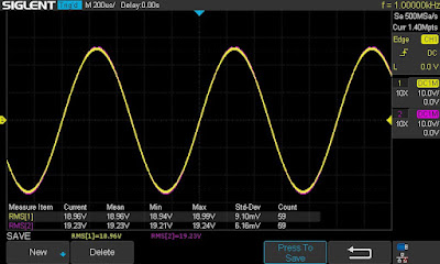
At the end of my restoration, I loaded this receiver with a low inductance 8Ω/100W dummy resistor for each channel, connected my oscilloscope across the speaker terminals, and applied a sine-wave signal of 1kHz to the AUX jacks. The output sine-wave signal was perfectly symmetrical on both channels with no clipping up to 21.23 VRMS (left channel) and 21.22 VRMS (right channel). It corresponds to the output power of 56.3W on the left channel and 56.3W on the right channel.

Output power test
Pioneer SX-750_Output Power Test

As usual, all the knobs and the front panel were gently cleaned in warm water with dish soap. All knobs were also slightly polished by Mothers Mag & Aluminum polish to remove some small spots of aluminum oxidation. All the pots and switches were also thoroughly cleaned with DeoxIT 5% contact cleaner and lubricated with DeoxIT FaderLube 5% spray.

The final result can be seen in the photos below. The sound is crystal clear, smooth, and well detailed. Please watch a short demo video at the end of this post. Thank you for reading.

Pioneer SX-750 - after restoration

Pioneer SX-750_After servicing_05

Pioneer SX-750_After servicing_01

Pioneer SX-750_After servicing_02

Pioneer SX-750_After servicing_03

Demo video after repair & restoration


Friday, August 27, 2021

JVC VR-5515X Receiver Restoration

Unit: AM/FM Stereo Receiver
Manufacturer: JVC
Model: VR-5515X
SN: 11600784

One of my customers rescued this beautiful vintage receiver and brought it for restoration. This is the first time I get this model on my workbench. There is very little information online about this receiver. It looks like this model was initially introduced on the market in 1975. The receiver produces 19.5 watts per channel into 8 ohms with no more than 0.8% total harmonic distortion. I was not able to find a service manual for this receiver. Only a schematic is available online at this time (August 2021) but for slightly different models VR-5515L and VR-5515LX.

JVC VR-5515X_After restoration

Initial Evaluation and Troubleshooting

Besides the common problems related to dirty/oxidized controls this unit also had the issue with the FM tuner. The tuner was tuning each station very well, and the stereo lamp came on as it should. The sound from both channels was crystal clear but after a few minutes, it started crackling. It was pretty noticeable at any volume especially in pauses between songs. The FM tuning needle was also twitching around zero. I decided to check the operating voltages on each transistor in the IF Amplifier circuit (transistors X101 thru X109). The voltage measured on the base, collector, and emitter of each transistor except one and was very close to the reference voltage on the schematic. However, the voltage measured on the base and emitter of transistor X106 was almost double of that on the schematic and fluctuated in a wide range. The original transistor installed in this position is 2SC711. It is not on my list of known transistors prone to failure but there is definitely something wrong with it. A good substitute for 2SC711 is a modern low noise Fairchild KSC1845 transistor. So, I replaced the suspect transistor and measured the operating voltages again. This time the voltage measured on the base, collector, and emitter of X106 was stable and very close to the reference voltages on the schematic. I tested the FM tuner for a while and no crackling sound was detected at any station. The FM tuning needle was also stable without any twitching.

Voltage measured on the base, collector, and emitter of X106 - before and after replacement:

X106, base, schematic: 4.0V
X106, collector, schematic: 13.0V
X106, emitter, schematic: 3.7V

2SC711, base: fluctuating from 8.2 to 8.9V
2SC711, collector: 12.2V
2SC711, emitter: fluctuating from 7.0 to 7.8V

KSC1845, base: 4.1V
KSC1845, collector: 12.3V
KSC1845, emitter: 3.5V

After the issue with the FM tuner was resolved I proceeded with a routine servicing on this unit.

Power Supply & Power Amplifier Board

The power supply and power amplifier circuits in this model are all on the same board. It is a pleasure to service this receiver (in comparison to some others) because each PCB has silk lettering on both sides for each electronic component. Not every manufacturer in the 70's followed this rule.

Silk lettering on the back (foil) side of PCB - service friendly receiver

JVC VR-5515X_Silk lettering on the back (foiled) side of PCB

The regulated power supply circuit provides +13V DC for the Tuner, and +20V DC for the Phono, Microphone, and Tone control amplifiers. It also supplies balanced power to the power amplifier from the bridge rectifier and two filter capacitors C627/C628. The circuit has 3 aluminum electrolytic capacitors C651, C654, and C657. I replaced them with low impedance and high-reliability Nichicon UPW/UPM caps. All original e-caps removed from this board were tested with Atlas ESR70 capacitance meter and results are below. All of them are still within the factory capacitance tolerance of +/- 20%.

Test results on original capacitors removed from the power supply circuit:

C651: rated capacitance – 470uF, measured – 531uF, ESR – 0.01Ω, deviation: +13%
C654: rated capacitance – 470uF, measured – 524uF, ESR – 0.01Ω, deviation: +12%
C657: rated capacitance – 470uF, measured – 506uF, ESR – 0.06Ω, deviation: +8%

The power amplifier circuit has eight aluminum e-caps C601/C602, C607/C608, C611/C612, C621, and C622. Two of them (the e-caps C601 and C602) are installed in the signal path. For some reason, regular aluminum electrolytic capacitors were installed in these positions by the manufacturer instead of low leakage e-caps. I think this is a result of a cost reduction strategy by JVC in the middle of 70's. I replaced these two e-caps with high-quality film polyester WIMA MKS2 caps to improve a signal-to-noise ratio. The remaining six e-caps were replaced with low impedance Nichicon UPW/UPM caps. Note, that almost all original e-caps removed from this board are slightly outside of factory capacitance tolerance.

Test results on original capacitors removed from the power amplifier circuit:

C601: rated capacitance – 1uF, measured – 1.24uF, ESR – 1.61Ω, deviation: +24%
C602: rated capacitance – 1uF, measured – 1.24uF, ESR – 1.55Ω, deviation: +24%
C607: rated capacitance – 220uF, measured – 270uF, ESR – 0.11Ω, deviation: +23%
C608: rated capacitance – 220uF, measured – 268uF, ESR – 0.12Ω, deviation: +22%
C611: rated capacitance – 47uF, measured – 51uF, ESR – 0.24Ω, deviation: +9%
C612: rated capacitance – 47uF, measured – 54uF, ESR – 0.18Ω, deviation: +15%
C621: rated capacitance – 220uF, measured – 265uF, ESR – 0.13Ω, deviation: +21%
C622: rated capacitance – 100uF, measured – 127uF, ESR – 0.06Ω, deviation: +27%

Two pre-driver transistors X601 and X602 installed in the power amplifier circuit are notorious 2SA726F transistors. These transistors get very noisy over time. I replaced them with modern low noise Fairchild KSA992 transistors. Watch the pinout on replacement transistors. The original transistor is BCE and the new one is ECB.

According to the schematic, the voltage on pin 660 should be +20V DC. I adjusted it to this value with a trimmer R654.

The voltage on pin 660 was adjusted to +20V DC

JVC VR-5515X_Voltage between the pin 660 and ground

Power supply & power amplifier board - before and after

JVC VR-5515X_Power Supply & Power Amplifier Board_before

JVC VR-5515X_Power Supply & Power Amplifier Board_after

Tone Amplifier Board

The tone amplifier board has ten aluminum electrolytic capacitors C501/C502, C506, C509/C510, C511/C512, C513/C514, and C525. Four of them C501, C502, C511, and C512 are installed in the signal path. Again, in these positions, the manufacturer installed just ordinary aluminum electrolytic capacitors instead of low leakage e-caps. Actually, I found only one low leakage e-caps and it was installed in the tuner circuit. All other e-caps in this receiver are just regular aluminum capacitors. Anyway, I always replace all e-caps installed in the signal path with either high-quality film polyester caps or low leakage e-caps. This is a crucial step to reduce the noise and improve the performance of any vintage receiver. So, the e-caps C501/C502 were replaced with film polyester WIMA MKS2 caps, and C511/C512 were replaced with low leakage Nichicon UKL caps. The remaining six aluminum e-caps were replaced with low impedance Nichicon UPW caps.

Test results on original capacitors removed from the tone amplifier board:

C501: rated capacitance – 1uF, measured – 1.1uF, ESR – 1.57Ω, deviation: +10%
C502: rated capacitance – 1uF, measured – 1.0uF, ESR – 1.58Ω, deviation: 0%
C506: rated capacitance – 10uF, measured – 13uF, ESR – 1.08Ω, deviation: +30%
C509: rated capacitance – 33uF, measured – 39uF, ESR – 0.78Ω, deviation: +18%
C510: rated capacitance – 33uF, measured – 43uF, ESR – 0.54Ω, deviation: +30%
C511: rated capacitance – 10uF, measured – 11uF, ESR – 0.64Ω, deviation: +10%
C512: rated capacitance – 10uF, measured – 11uF, ESR – 0.58Ω, deviation: +10%
C513: rated capacitance – 10uF, measured – 12uF, ESR – 0.64Ω, deviation: +20%
C514: rated capacitance – 10uF, measured – 11uF, ESR – 0.62Ω, deviation: +10%
C525: rated capacitance – 100uF, measured – 115uF, ESR – 0.19Ω, deviation: +15%

Four NPN transistors (X501 thru X504) installed on this board are notorious 2SC458 transistors. This transistor has different types of failure modes: leakage, noise, and static. I replaced every 2SC458 transistor with a modern low-noise Fairchild KSC1845. Watch the pinout on replacement transistors while servicing this board. The original transistor is BCE and the new one is ECB.

Tone amplifier board - before and after

JVC VR-5515X_Tone Amplifier Board_before

JVC VR-5515X_Tone Amplifier Board_after

Phono & Microphone Amplifier Board

The phono and microphone amplifier circuits in this receiver are assembled on the same board. It was quite challenging to work on this PCB since the working space is really very limited. Also, the dial string is located very close to the back (foiled) side of this board and there is a risk of burning the string with a hot soldering iron. It is impossible to remove this board from the chassis without disassembling the front metal panel with a dial string. I didn't want to do it and found a method to overcome it. The front metal panel is mounted on the chassis with four screws on each side. I unscrewed four screws on the right side (close to the variable capacitor) and moved the panel ahead a little bit. It was enough in order to remove the board from the chassis and get much better access for servicing. Be careful at this step while servicing this board. Don't move the front panel too much since there is also a risk to damage a dial string assembly.

Unscrew these four screws on the right side (the 4th screw is hidden on the upper side)

JVC VR-5515X_Unscrew these four screws on the right side

Phono & Microphone amplifier board - removed from the chassis

JVC VR-5515X_Phono & Microphone Amplifier Board_removed from the chassis

The microphone amplifier circuit has four aluminum e-caps C431, C435, C436, and C439. Two of them (the e-caps C431 and C436) are installed in the signal path. I replaced them with film polyester WIMA MKS2 caps. The remaining two aluminum e-caps were replaced with low impedance Nichicon UPW caps.

Test results on original capacitors removed from the microphone amplifier circuit:

C431: rated capacitance – 1uF, measured – 1uF, ESR – 1.57Ω, deviation: 0%
C435: rated capacitance – 33uF, measured – 42uF, ESR – 0.64Ω, deviation: +27%
C436: rated capacitance – 1uF, measured – 1uF, ESR – 1.77Ω, deviation: 0%
C439: rated capacitance – 100uF, measured – 112uF, ESR – 0.15Ω, deviation: +12%

This board has a bunch of notorious 2SC458 transistors. Two of them X431 and X432 are installed in the microphone circuit. And four X401 thru X404 are installed in the phono circuit. I replaced each 2SC458 transistor with a modern low noise Fairchild KSC1845. Again, pay attention to the pinout on replacement transistors while servicing this board.

The phono amplifier board has nine aluminum e-caps C401/C402, C409/C410, C413/C414, C419, and C425/C426. Four of them C401/C402 and C413/C414 are installed in the signal path. I replaced them with film polyester WIMA MKS2 caps. The other five aluminum e-caps were replaced with low impedance Nichicon UPW caps.

Test results on original capacitors removed from the phono amplifier circuit:

C401: rated capacitance – 1uF, measured – 1.1uF, ESR – 1.58Ω, deviation: +10%
C402: rated capacitance – 1F, measured – 1.1uF, ESR – 1.72Ω, deviation: +10%
C409: rated capacitance – 10uF, measured – 12uF, ESR – 1.46Ω, deviation: +20%
C410: rated capacitance – 10uF, measured – 12uF, ESR – 1.44Ω, deviation: +20%
C413: rated capacitance – 1uF, measured – 1.1uF, ESR – 1.75Ω, deviation: +10%
C414: rated capacitance – 1uF, measured – 1.1uF, ESR – 1.63Ω, deviation: +10%
C419: rated capacitance – 220uF, measured – 242uF, ESR – 0.11Ω, deviation: +10%
C425: rated capacitance – 10uF, measured – 11uF, ESR – 1.56Ω, deviation: +10%
C426: rated capacitance – 10uF, measured – 12uF, ESR – 1.43Ω, deviation: +20%

Phono & Microphone amplifier board - before and after

JVC VR-5515X_Phono & Microphone Amplifier Board_before

JVC VR-5515X_Phono & Microphone Amplifier Board_after

Dial and Meter Lamps

It is pretty simple to replace the dial bulbs on this model. One just needs to straighten four metal petals and release the long narrow PCB holding four dial bulbs. I replaced the original bulbs with new incandescent lamps.

Long narrow PCB holding four dial bulbs - just straighten four metal petals to release it

JVC VR-5515X_PCB holding four dial bulbs

New dial bulbs installed

JVC VR-5515X_New dial bulbs installed

The signal and tuning meter lamps can be replaced even easier than the dial lamps. I also replaced the e-cap C55 across the meter leads with a new Nichicon UPW cap.

Signal and tuning meter bulbs - original and new

JVC VR-5515X_Meter Bulbs and E-cap_original

JVC VR-5515X_Meter Bulbs and E-cap_new

Idling Current Adjustment

As I mentioned earlier I didn't find the service manual for this model. The typical idling current is usually ranging from ~20 to 30mA. It is controlled with trimmers R619 (left channel) and R620 (right channel) on this model. The resistance of each emitter resistor is 0.22Ω. Therefore, the voltage across each emitter resistor should be ~4.4mV (0.02A x 0.22Ω = 0.0044V). I adjusted it to ~5mV on each channel. It roughly corresponds to an idling current of 23mA.

Idling current adjustments on the left and right channel

JVC VR-5515X_Idling Current Adjustment_pin 609 & 611_Left_trimmer R619

JVC VR-5515X_Idling Current Adjustment_pin 610 & 612_Right_trimmer R620

Output Power Test

At the end of my restoration, I loaded this receiver with a low inductance 8Ω/100W dummy resistor for each channel, connected my oscilloscope across the speaker terminals, and applied a sine-wave signal of 1kHz to the AUX jacks. The output sine-wave signal was perfectly symmetrical on both channels with no clipping up to 11.02 VRMS (left channel) and 10.94 VRMS (right channel). It corresponds to the output power of 15.2W on the left channel and 15.0W on the right channel.

Output power test

JVC VR-5515X_Output Power Test

As usual, all the knobs and the front panel were gently cleaned in warm water with dish soap. All controls have been cleaned with DeoxIT 5% contact cleaner and lubricated with DeoxIT FaderLube 5% spray. 

All issues with electronics have been solved and the receiver works normally again. The final result can be seen in the photos below. Please watch a short demo video at the end of this post. Thank you for reading.

JVC VR-5515X - after restoration

JVC VR-5515X_After restoration

JVC VR-5515X_After restoration_02

Demo video after repair & restoration