Manufacturer: Pioneer
Model: SX-880
SN: YE3607162S
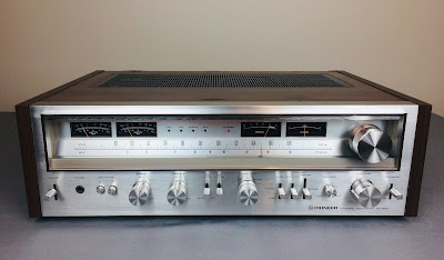
Today I'm showcasing a Pioneer SX-880 receiver that came in for restoration. The SX-880 is a big brother of Pioneer SX-780 which I restored about a year ago. It produces 60 watts per channel into 8 ohms with no more than 0.05% total harmonic distortion. It was manufactured from 1978 through 1979. The list price in 1978 was $425.00. According to the Pioneer database, this unit was manufactured in May 1978.
Initial Evaluation and Cleaning
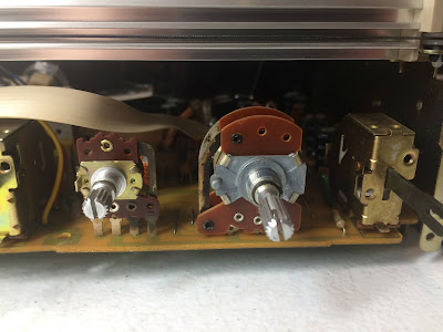
This particular unit came in with several problems and most of them were related to the dirty and/or oxidized switches and pots. The sound from both channels was very distorted and intermittent. Occasionally one channel cuts out the sound completely. The initial evaluation showed that the contacts in all three switches (TAPE MONITOR, TAPE DUPLICATE, and MODE) are severely oxidized due to age. The BALANCE and VOLUME pots were dirty as well. All other switches and pots were in good shape. So, I decided to start the restoration from a good cleaning of all switches and pots to see if there are any other issues related to the sound in this unit.
First of all, I carefully vacuumed this unit inside and cleaned all boards as much as possible from the dust. It is always worth cleaning any vintage gear before servicing. Dust can carry a static charge and short-circuit the electronics. That's why all PCBs should be kept clean from dust as much as possible.
Tuner board - before and after cleaning
Variable capacitor - before and after cleaning
Transformer & Filter capacitors - before and after cleaning
To clean the pots and switches in SX-880 the wooden cover should be removed. However, all potentiometers might be much easier to clean if both the front panel and large mounting plate are also removed. In addition, it will provide excellent access to all electronic components located close to the mounting plate.
Black mounting plate removed - much easier to clean all pots and switches, and replace all e-caps
I thoroughly cleaned all pots and switches with DeoxIT 5% contact cleaner and lubricated them with DeoxIT FaderLube 5% spray. A quick test showed that a clear sound was restored from both channels.
AF Amplifier Board GWK-119
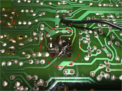
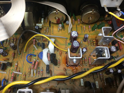
The next issue was related to three transistors Q26, Q27 and Q30 installed in the power supply circuit. These transistors are running very hot under normal operating conditions. The original heat sink attached to each transistor is rather small to efficiently dissipate the heat. As a result, a PCB discoloration is often observed around those transistors. In extreme cases the PCB around transistor Q26 could be severely damaged and the solder joint cracks can often be detected. It results in intermittent contact problems. I decided to retire those three transistors and replace them with modern Fairchild transistors. Two NPN transistors Q26 and Q30 were replaced with KSC2073TU, and one PNP transistor Q27 was replaced with KSA940TU. A new silicone thermal compound (Wakefield-Vette, 120 series) was applied between each transistor and the heat sink.
PCB discoloration around transistor Q26
Original transistors Q26, Q27, and Q30 from the power supply were replaced with modern Fairchild transistors
The power supply circuit has ten electrolytic capacitors: C407 thru C410, C413, C414, and C420 thru C423. All of them were replaced with low impedance and high-reliability Nichicon UPW/UPM caps. Those e-caps are designed for switching power supplies and can operate in the temperature range from -55 to +105 C. The original e-caps installed in vintage gears from the 70's have a maximum operating temperature of +85C.
I found an error in the schematic concerning the e-cap C410. The schematic shows this capacitor as 100uF/16V despite the original capacitor installed on the board being 220uF/16V. Most probably this is just due to design improvements not well documented by Pioneer. I replaced this e-cap with a Nichicon UPW capacitor, 220uF/25V.
All original e-caps were tested with Atlas ESR70 capacitance meter and results are below. Most of them are still within the factory capacitance tolerance. However, the modern low impedance Nichicon capacitors have lower ESR and more tight spec on capacitance tolerance.
Test results on original capacitors removed from the power supply circuit:
C407: rated capacitance – 470uF, measured – 289uF, ESR – 0.06Ω, deviation: -39%
C408: rated capacitance – 330uF, measured – 320uF, ESR – 0.06Ω, deviation: +3%
C409: rated capacitance – 100uF, measured – 99uF, ESR – 0.23Ω, deviation: -1%
C410: rated capacitance – 220uF, measured – 139uF, ESR – 0.33Ω, deviation: -37%
C413: rated capacitance – 3.3uF, measured – 4.1uF, ESR – 1.55Ω, deviation: +24%
C414: rated capacitance – 3.3uF, measured – 4.2uF, ESR – 1.11Ω, deviation: +27%
C420: rated capacitance – 47uF, measured – 38uF, ESR – 0.26Ω, deviation: -19%
C421: rated capacitance – 47uF, measured – 37uF, ESR – 0.36Ω, deviation: -21%
C422: rated capacitance – 100uF, measured – 119uF, ESR – 0.14Ω, deviation: +19%
C423: rated capacitance – 100uF, measured – 97uF, ESR – 0.18Ω, deviation: -3%
The protection circuit has five electrolytic capacitors: C415 thru C419. Two of them (C415 and C416) are solid tantalum capacitors. I replaced these e-caps with high-quality film polyester Kemet caps. The remaining e-caps were replaced with Nichicon UPW caps.
The FM muting circuit has five electrolytic capacitors: C301 thru C305. Two of them C302 and C303 are low leakage e-caps. I replaced C302/C303 and C304/C305 with film polyester WIMA MKS2 caps. The remaining capacitor C301 was replaced with a low impedance Nichicon UPW cap.
The phono amplifier circuit has eight electrolytic capacitors: C101/C102, C105/C106, C115/C116, and C119/C120. Four of them C101/C102 and C115/C116 are low leakage capacitors installed in the signal path. I replaced them with modern low leakage Nichicon UKL caps. The other four aluminum e-caps were replaced with low impedance Nichicon UPW caps. The Nichicon UKL caps have lower ESR which is beneficial for capacitors installed in the signal path of the circuit. For example, the original low leakage e-cap with capacitance 2.2uF/50V has the ESR in the range from 2.2 to 2.4Ω. The modern Nichicon UKL cap with the same capacitance of 2.2uF/50V has a typical ESR ranging from 1.0 to 1.2Ω.
Test results on original capacitors removed from the phono amplifier circuit:
C101: rated capacitance – 2.2uF, measured – 2.2uF, ESR – 2.2Ω, deviation: 0%
C102: rated capacitance – 2.2uF, measured – 2.2uF, ESR – 2.3Ω, deviation: 0%
C105: rated capacitance – 470uF, measured – 544uF, ESR – 0.18Ω, deviation: +16%
C106: rated capacitance – 470uF, measured – 560uF, ESR – 0.15Ω, deviation: +19%
C115: rated capacitance – 2.2uF, measured – 2.3uF, ESR – 2.2Ω, deviation: +5%
C116: rated capacitance – 2.2uF, measured – 2.2uF, ESR – 2.4Ω, deviation: 0%
C119: rated capacitance – 100uF, measured – 124uF, ESR – 0.18Ω, deviation: +24%
C120: rated capacitance – 100uF, measured – 131uF, ESR – 0.18Ω, deviation: +31%
The tone control circuit has twelve electrolytic capacitors: C205/C206, C209/C210, C215/C216, C217/C218, C227/C228, and C229/C230. All of them (except C209/C210 and C215/C216) are low leakage capacitors installed in the signal path. I replaced e-caps C205/C206 with film polyester WIMA MKS2 caps, C217/C218 and C227/C228 with low leakage Nichicon UKL caps, and C229/C230 with film polyester Kemet caps.
Ideally, all electrolytic capacitors installed in the signal path should be replaced with high-quality film capacitors. However, the size of modern film capacitors with capacitance 2.2uF and higher is rather large and does not always fit the position of the original e-cap. Therefore, I usually replace all capacitors with capacitance 1uF and lower with high-quality film polyester capacitors (WIMA or Kemet). The modern film polyester capacitors have excellent properties and zero ESR. All other capacitors with capacitance 2.2uF and higher installed in the signal path are usually replaced with low leakage Nichicon UKL caps.
Two pictures below show the measured capacitance and ESR of the original low leakage e-cap C205 (1uF/50V) and modern film polyester capacitor with the same rated capacitance and operating voltage. The original e-cap still holds the rated capacitance close to 1uF (the tolerance is just +15%) but its ESR is rather high - 5.1Ω. The modern WIMA film cap has zero ESR and a very tight spec on capacitance tolerance.
Original low leakage e-cap C205, 1uF/50V - the ESR is high
WIMA film polyester capacitor, 1uF/50V - the ESR is zero
Several pictures below show the AF Amplifier board before and after service.
AF Amplifier Board - before servicing
AF Amplifier Board - after servicing
Meter Assembly Board GWX-193
The meter assembly board is mounted on the chassis with three plastic clips. The board is hard to service without removing it from the chassis. I carefully pulled off those three clips using two small flat screwdrivers. The plastic clips are very easy to break since they became rather brittle due to aging. So, take your time and work slowly if you need to need to service this board. It has only four electrolytic capacitors C501 thru C504 which were replaced with low impedance Nichicon UPW caps.
Meter assembly board - after servicing
Dial Lamps
The old dial bulbs in this unit were replaced with new incandescent lamps. To reflect the light and diffuse the heat coming from these bulbs I attached a strip of foil tape inside the top cover. It substantially reduces the heat coming from incandescent bulbs and protects the top cover and veneer from heat damage.
DC Balance and Idle Current Adjustments
The DC balance and idle current were adjusted according to the service manual. No dummy load or input signal is required for this adjustment.
The DC balance is measured between pin 5 and ground on the left channel, and between pin 12 and ground on the right channel. It should be adjusted as close to zero volts as possible. The blue trimmers VR5 and VR6 are used for this adjustment on the left and right channel, respectively. I adjusted the DC balance to ~3mV on each channel.
The idle current (or strictly speaking the bias) is measured between pins 8 and 10 on the left channel, and between pins 14 and 16 on the right channel. This voltage was adjusted to ~32mV with trimmer VR7 (left channel) and VR8 (right channel), respectively.
DC balance on the left and right channel after restoration
Idle current (Bias) on the left and right channel after restoration
Power Meters Adjustment
An AC voltmeter and function generator are required to adjust power meters. A sine-wave signal of 1 kHz, 150mV should be applied to the AUX terminals. The level of this signal should be adjusted so that the voltage on the SPEAKERS terminals reads 21.9 VRMS. Then, the trimming resistors VR9 and VR10 should be adjusted so that the power meters read 60W.
As usual, all the knobs and the faceplate were gently cleaned in warm water with dish soap. I also slightly polished all knobs by Mothers Mag & Aluminum polish to remove some small spots of aluminum oxidation.
The final result can be seen in the photos below. Please watch a short demo video at the end of this post. Thank you for reading.
Pioneer SX-880 - after restoration
Demo video after repair & restoration

